
Light condensing optical system, laser processing method and apparatus, and method of manufacturing fragile material

a technology of laser processing and optical system, which is applied in the field of condensing optical system, laser processing method and equipment, and manufacturing method of fragile materials, can solve the problems of difficult processing of materials with a large thickness, inconvenient, and small spot intensity, and achieve the effect of reducing the spot intensity

Active Publication Date: 2010-03-18
SUMITOMO ELECTRIC IND LTD +1
View PDF5 Cites 20 Cited by
  • Summary
  • Abstract
  • Description
  • Claims
  • Application Information

AI Technical Summary

Benefits of technology

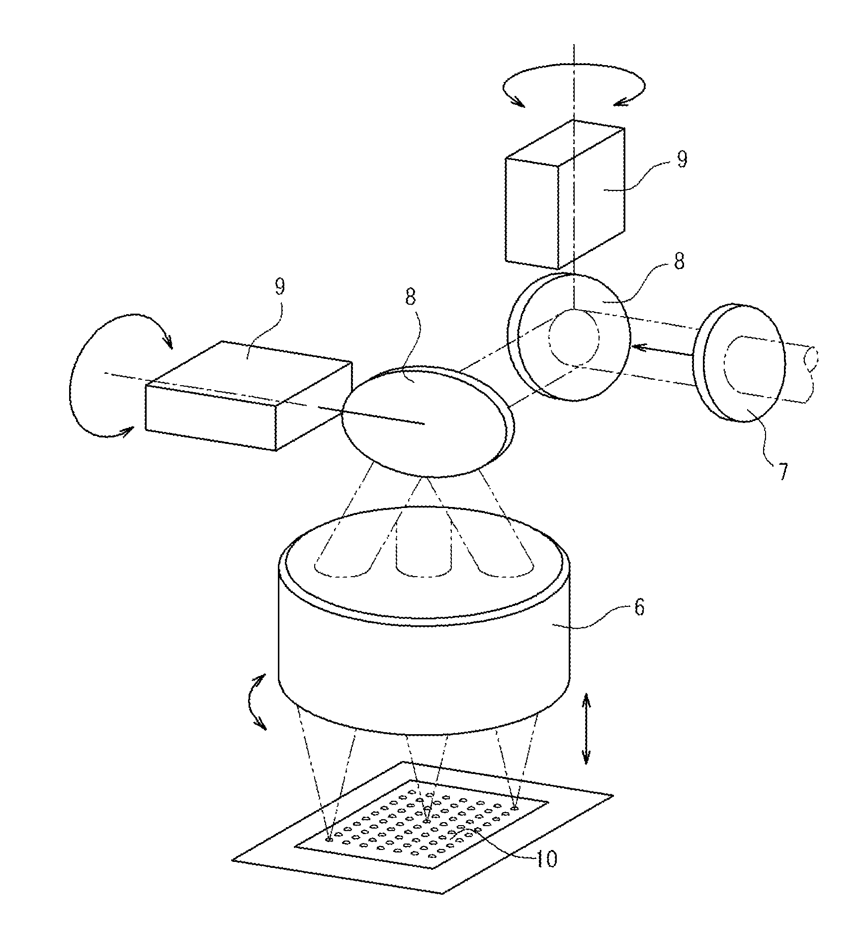
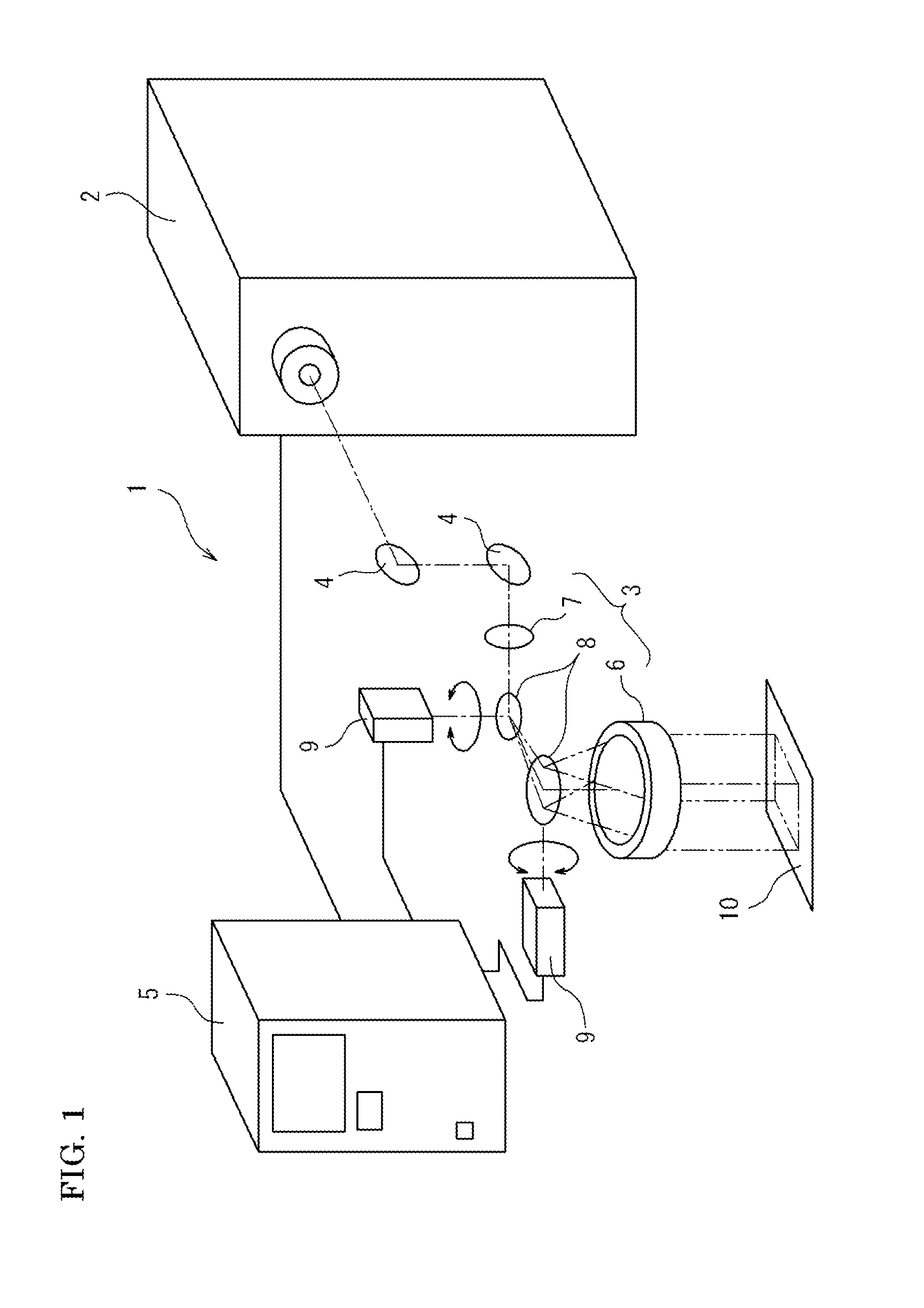
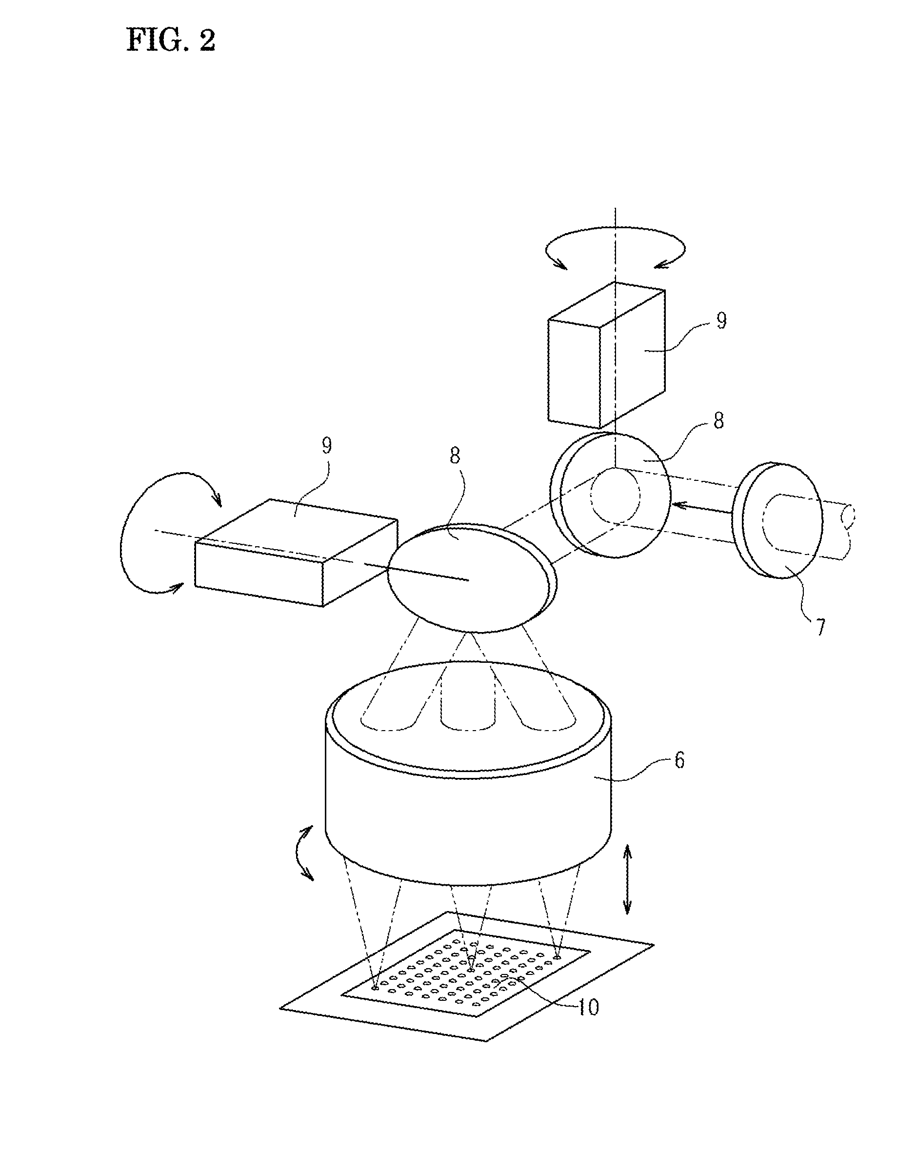
The present invention provides a condensing optical system with a small spot size and a large focal depth without causing discontinuity of intensity distribution or decreasing the intensity of the spot. The system uses a spherical aberration producing function to increase the focal depth while keeping the size of the focal point small. The system also includes a laser processing method that uses an asymmetric laser beam with high peak power density to efficiently absorb energy and prevent chipping, taper, or dulling at the laser exit side. The system and method can be used in various applications such as laser cutting and surface annealing.

Problems solved by technology

In addition, it is difficult to process a material with a large thickness.
However, with the condensing optical system disclosed in Japanese Patent No. 2664625, the laser beam is divided at the lens surface and their focuses are discontinuously connected.
Thus, the intensity of the spot is considerably small, and is not suitable for processing which requires high intensity.
Hence, it is difficult to machine such a material.
When a brittle material is cut with a laser beam passing through the condensing lens with the characteristic, a defect, such as chipping, taper (inclination with respect to an expected work surface), or dulling, may occur in a cut surface at a laser exit side.
When a brittle material is laser processed to make a cutting tool, merely cutting the material is insufficient.
If a defect occurs at an edge portion, repairing the defect may need considerable work hours and costs.
When the width of cutting is increased, a loss of the material is increased.
Further, with the conventional method, although the occurrence of taper or dulling may be suppressed by a certain degree, it is difficult to completely prevent such a defect.

Method used


Image

  • Light condensing optical system, laser processing method and apparatus, and method of manufacturing fragile material
  • Light condensing optical system, laser processing method and apparatus, and method of manufacturing fragile material
  • Light condensing optical system, laser processing method and apparatus, and method of manufacturing fragile material

Examples


example

[0120]An optical system shown in FIG. 37 was used to cut single crystal diamond. Single crystal diamond 11 had a thickness of 0.8 mm. The single crystal diamond 11 was synthetic single crystal diamond formed by melting a raw material carbon into a metal solvent at a very high pressure of 5 GPa or higher and a high temperature of 1300° C. or higher and causing the raw material carbon to grow on a seed crystal in the metal solvent by a temperature difference method. The single crystal diamond 11 was placed on a glass substrate 12 with a thickness of 3 mm.

[0121]A YAG laser oscillator 13 with an output of 7 W was used as the laser oscillator. A laser beam 17a generated by the YAG laser oscillator 13 was a pulse laser with a repetition period of 3 kHz having a fundamental wavelength of 1064 nm. The diameter of the laser beam 17a to be generated was increased five times by a beam expander 14, thereby providing a laser beam 17b with a diameter of 10 mm. The direction of the laser beam 17b ...


PUM

PropertyMeasurementUnit
wavelengthaaaaaaaaaa
focal lengthaaaaaaaaaa

Abstract

A condensing optical system having a condensed light spot with a small size and a large focal depth without causing a problem of a decrease in intensity of the condensed light spot or discontinuity of an intensity distribution in front and rear areas of a focal position is provided. The condensing optical system that condenses a laser beam generated by a laser source at a predetermined focal length is designed to satisfy Expressions (a) to (d), thereby producing 3rd and 5th spherical aberrations:|Z8|≧0.1λ or |Z15|≧0.05λ,   (a)Z8 / Z15≧3 or Z8 / Z15<1,   (b)|Z8|<1.4λ, and   (c)|Z15|<0.5λ,   (d)where λ is a wavelength, Z8 is an 8th coefficient of coefficients of the Zernike fringe polynomial of wavefront aberration corresponding to a 3rd order spherical aberration, and Z15 is a 15th coefficient of the coefficients of the Zernike fringe polynomial of wavefront aberration corresponding to a 5th spherical aberration.

Description

TECHNICAL FIELD[0001]The present invention relates to a condensing optical system, laser processing method and apparatus, and a manufacturing method of a brittle material blank. More particularly, the present invention relates to a condensing optical system that condenses a laser beam into a very small spot with a large focal depth; to laser processing method and apparatus that cut a workpiece made of a brittle material such as single crystal diamond or form a groove in a surface of the brittle material with the condensed laser beam; and to a manufacturing method that manufactures various members made of the brittle material.BACKGROUND ART [0002]Laser beams are applied to various fields today. For example, a laser processing technique is developing rapidly. The laser processing technique is desired to provide processing to a smaller material with a higher precision. It is necessary to condense a laser beam into a smaller spot. To attain this, a method is conceivable in which a numer...

Claims


Application Information

Patent Timeline
Patent Type & Authority Applications(United States)
IPC IPC(8): B23K26/00G02B19/00
CPCB28D5/00G02B26/101B23K26/0648B23K26/4075B23K26/0815B23K26/38B23K26/0665B23K26/40B23K26/0821B23K2103/50
Inventor WATATANI, KENICHIFUSE, KEIJIKOBAYASHI, YUTAKA
Owner SUMITOMO ELECTRIC IND LTD
Learn More