
Printable medium for etching oxidic, transparent and conductive layers

a technology of transparent and conductive layers and printing medium, which is applied in the field of printing, can solve the problems of limiting the applicability, affecting the effect of good electrical conductivity of indium oxide crystal structure, and limiting the application of polymer-based (epoxy or phenolic resin) metallisation pastes, so as to achieve good properties and good properties

Inactive Publication Date: 2010-03-18
MERCK PATENT GMBH
View PDF15 Cites 46 Cited by
  • Summary
  • Abstract
  • Description
  • Claims
  • Application Information

AI Technical Summary

Benefits of technology

[0054]In a particular embodiment, etching media of this type comprise graphite or carbon-black powder having relative particle diameters of less than 50 nm and a specific BET surface area in the range from 50 to 70 m2 / g. It has proven particularly advantageous for the graphite or carbon-black powder present to have relative particle diameters in the range from 30 nm to 45 nm. Etching media comprising carbon-black powder having a relative particle diameter of 40 nm and a specific BET surface area of 62 m2 / g have very particularly good properties. While higher proportions of solids were necessary in earlier compositions, the addition of less than 8% by weight, but more than 0.5% by weight, of graphite or carbon-black powder having the said properties gives, in accordance with the invention, compositions which can be printed in the form of extremely fine lines. Compositions which have a graphite or carbon-black powder content in the range from 3 to 7% by weight and a viscosity in the range from 25 to 35 Pas have particularly good properties. Corresponding compositions can advantageously be used for etching ITO layers at temperatures between 120-170° C.DESCRIPTION OF THE INVENTION
[0074]It goes without saying per se to the person skilled in the art that these additives may also be replaced by other commercially available products with the same action. It is essential in this connection that the addition of such additives improves the product properties.

Problems solved by technology

The tin(IV) oxide, as dopant, produces the flaws necessary for good electrical conductivity in the crystal structure of the indium oxide.
However, ITO can also be applied by high-vacuum vapour deposition, although the components coated by vapour deposition have to be warmed to up to 360° C., which restricts the applicability.
Due to the high temperatures, polymer-based (epoxy or phenolic resin) metallisation pastes therefore cannot be used for this purpose.
Crystal defects and metallic contamination in the underlying silicon also arise during performance of the fire-through process.
As a consequence of the system, the passivation layer is in addition totally destroyed by the printed-on metal paste on top.
Glasses below are taken to mean silicon oxide- and silicon nitride-containing materials which are in the solid amorphous physical state without the glass components crystallising out and have a high degree of disorder in the microstructure owing to the lack of long-range order.
The use of etchants, i.e. chemically aggressive compounds, results in the dissolution of the material exposed to the etchant attack.
In the laser-supported etching methods, the laser beam scans the entire etching pattern on the glass dot by dot or line by line in the case of vector-orienting systems, which, besides a high degree of precision, also requires considerable adjustment effort and time.
The wet-chemical and dry-etching methods include material-intensive, time-consuming and expensive process steps:
The disadvantages of the etching methods described are due to the time-consuming, material-intensive and expensive process steps, which are in some cases very complex in technological and safety terms and, in addition, are frequently carried out discontinuously.
In particular on printing of surfaces, use of these particle-free media gives rise to problems due to inadequate resilience of the printed lines, dots or structures (inadequate structure fidelity), meaning that a significant broadening of the originally printed lines occurs (running of the etching species on the substrate).
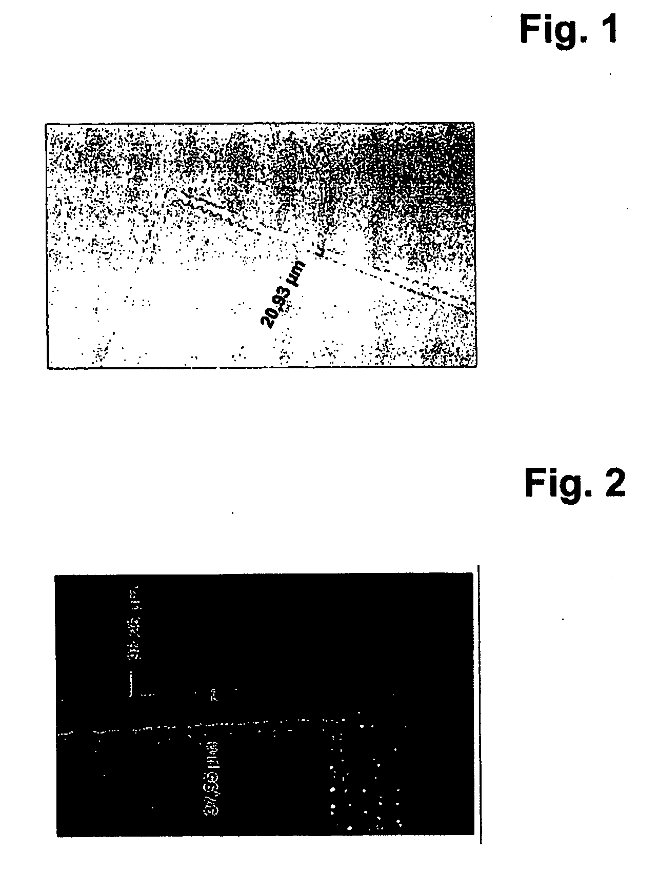
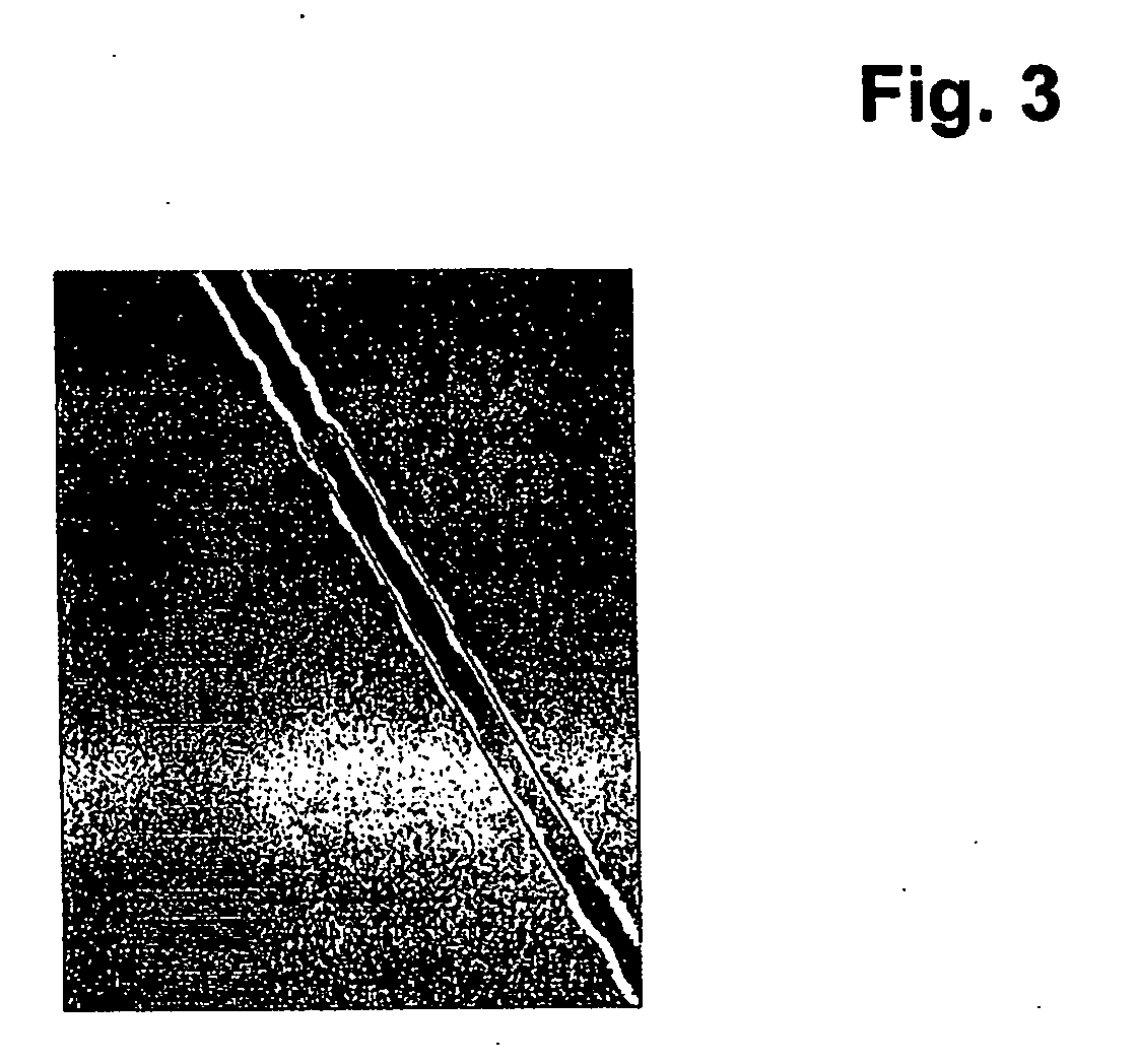
Experiments have shown that these etching pastes are not suitable for etching very thin lines having a width of less than 1 mm cleanly and without flaws, irrespective of whether polymer particles having a diameter of 0.01 μm or of 30 μm are employed for the preparation of the pastes.

Method used


Image

  • Printable medium for etching oxidic, transparent and conductive layers
  • Printable medium for etching oxidic, transparent and conductive layers

Examples


example 1

[0085]Etching paste comprising an inorganic nanoparticulate solid additive

[0086]218 g of deionised water

[0087]223 g of 1-methyl-2-pyrrolidone

[0088]1.6 g of ethylene glycol

[0089]The following are added successively with stirring to this solvent mixture:

[0090]465 g of phosphoric acid (85%)

[0091]and

[0092]11 g of polyvinylpyrrolidone,

where polyvinylpyrrolidone is incorporated with vigorous stirring.

[0093]50 g of carbon black

[0094]are then added to the clear homogeneous mixture, which is stirred for a further 2 hours.

[0095]The ready-to-use paste can be printed using a 280 mesh stainless-steel fabric screen. In principle, polyesters or similar screen materials can also be used. The crucial factor is that the screen material selected is inert to the etching component present in the etching composition.

[0096]The etching paste prepared has proven to be stable on storage over a long period with retention of the advantageous etching properties. Further examples of compositions according to the...


PUM

PropertyMeasurementUnit
Temperatureaaaaaaaaaa
Percent by massaaaaaaaaaa

Abstract

The present invention relates to novel printable etching media having improved properties for use in the process for the production of solar cells. These are corresponding particle-containing compositions by means of which extremely fine lines and structures can be etched very selectively without damaging or attacking adjacent areas.

Description

[0001]The present invention relates to novel printable etching media having improved properties for use in the process for the production of solar cells. These are corresponding particle-containing compositions by means of which extremely fine lines and structures can be etched very selectively without damaging or attacking adjacent areas.PRIOR ART AND OBJECT OF THE INVENTION[0002]During the process for the production of solar cells, it is necessary, inter alia, to structure oxide layers on a support material. A crystalline silicon solar cell usually consists of a p-conducting substrate into which a layer of an n-conducting substance, for example phosphorus, of homogeneous thickness is diffused on the front. In order to conduct away the current generated during incidence of light, metallically conducting contacts are applied to the front and back of the wafer. For the purposes of an inexpensive production method which is suitable for mass production, the contacts are usually produce...

Claims


Application Information

Patent Timeline
IPC IPC(8): H01L21/306C09K13/04H01B13/00
CPCC03C15/00Y02E10/50H01L31/1884C09K13/04C09K13/06H01L21/30604
Inventor STOCKUM, WERNERKUEBELBECK, ARMIN
Owner MERCK PATENT GMBH
Learn More