Acne Treatment Method, System and Device

a technology for treating acne and skin conditions, applied in the field of dermatologic treatment devices and methods, can solve the problems of unattractive long-term use treatment, ineffective or undesirable in some individuals even for short-term use, and based devices and techniques, so as to reduce the development of new lesions, reduce the treatment time, and avoid any hyperpigmentation of the skin

Inactive Publication Date: 2010-03-18
CHANNEL INVESTMENTS LLC
View PDF102 Cites 78 Cited by
  • Summary
  • Abstract
  • Description
  • Claims
  • Application Information

AI Technical Summary

Benefits of technology

[0015]In this second embodiment, operation of the device and exposure time are controlled, in part, through the use of timing cartridges, which are inserted into the device to activate and enable treatment. The timing cartridges can be configured in multiple ways, depending upon the particular implementation. In some instances, the timing device is configured as a timer and limits the treatment time. In other instances, the timing cartridge is programmed to provide controlled treatment regimens. A treatment method using the second embodiment includes moving the output window over a selected treatment area while applying light energy, with an option to dwell on lesions. In some embodiments of the method, the rest of the surrounding area, such as the face, or other affected area, is also treated with a reduced total dosage amount to provide preventative care by reducing P. acnes bacteria levels, thereby lessening the development of new lesions. The second embodiment is particularly efficaciou

Problems solved by technology

Acne is an age old problem of many adolescents and adults.
While some are effective for a percentage of the population, for at least a period of time, each typically involves a side effect profile that makes the treatment unattractive for long term use and ineffective or undesirable in some individuals even for short term use.
More recently, various light-based devices and techniques have been suggested, although none, so far, have proven significantly effective.
It is also possible that photo-excited porphyrin is itself toxic to bacteria or produces a toxi

Method used


Image

  • Acne Treatment Method, System and Device
  • Acne Treatment Method, System and Device
  • Acne Treatment Method, System and Device

Examples


first embodiment

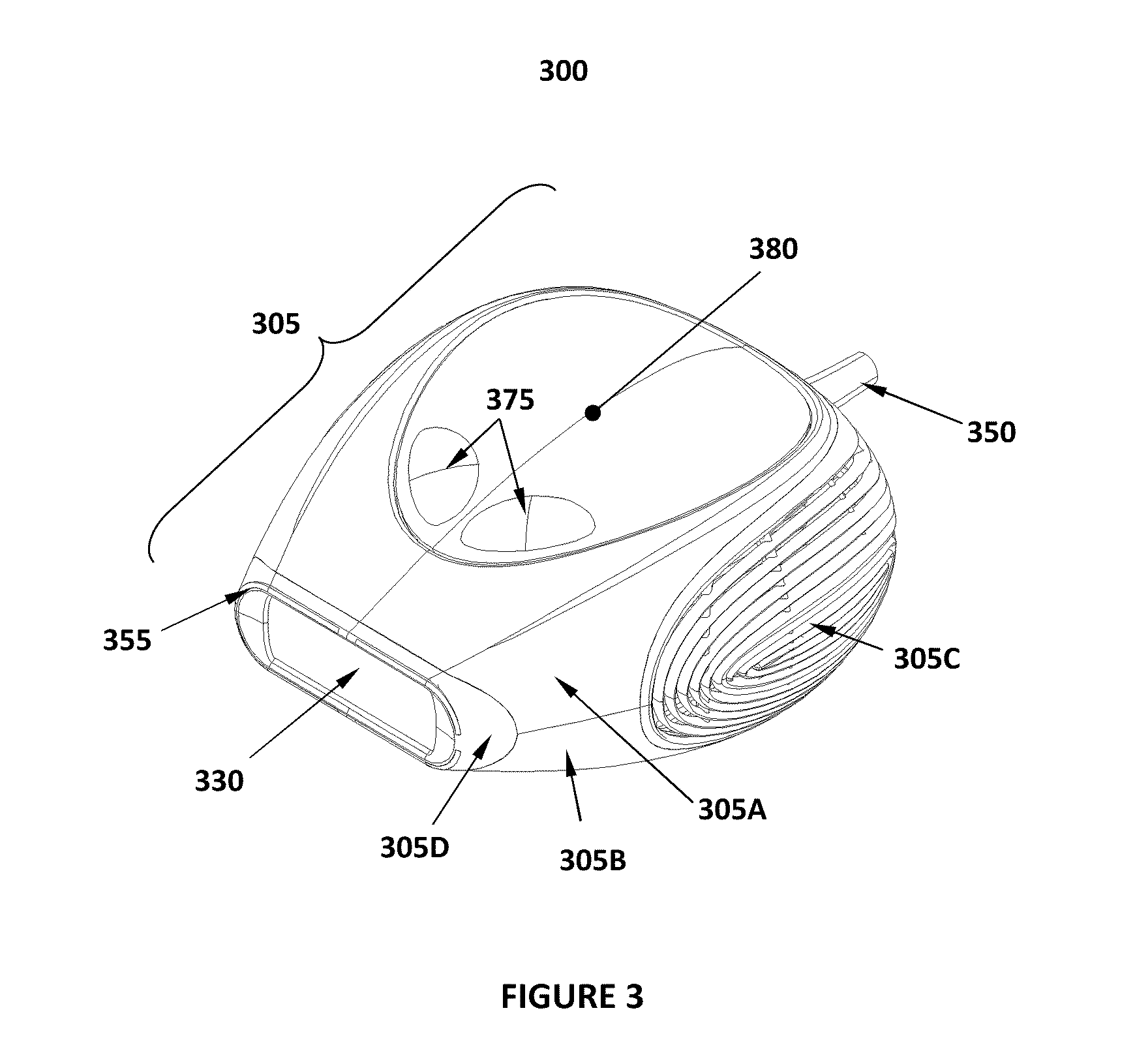
[0049]Referring next to FIGS. 3 and 4, a first embodiment of a treatment device in accordance with the invention can be better appreciated. In particular, the device 300, shown in exploded perspective view in FIG. 4, comprises a housing 305 which in an embodiment, is comprised of a top housing 305A, a bottom housing 305B, a vent 305C and a nosepiece 305D, which provides an output aperture 305E. For the illustrated embodiment, the housing is configured to be hand held. It will be appreciated that other embodiments need not be entirely hand held, but can comprise a base station and hand-held head unit connected by an umbilical, or any other suitable physical arrangement.

[0050]Inside the housing 305 of the illustrated embodiment is a circuit board 315 onto which is mounted a light source 310, which can, for example, be one or more devices such as an LED, an LED array, or other suitable source including one or more laser diodes, flashlamps, or other light emitting devices. In at least s...

second embodiment

[0075]Referring now to FIGS. 9 through 11, an exemplary second embodiment of a treatment device in accordance with the invention can be better appreciated. In particular, the device 400, shown in exploded perspective view in FIG. 11, comprises a housing 405, which is comprised of an upper housing 405A, a lower housing 405B, cap 405C, which provides cap aperture 405D, and a nosepiece 405E, which provides an output aperture 405F. Suitable materials for the housing 400 include, but are not limited to, polymers and polymer blends, such as a polycarbonate / ABS (acrylonitrile butadiene styrene) blend, and it will be recognized by those skilled in the art that other materials, such as light-weight metals and other plastics can also be utilized for the housing. In the illustrated embodiment, the bezel or front of the nosepiece 405E is made of nonconductive material such as plastic, although in other embodiments the nosepiece 405E can be made of metal or metalized plastic.

[0076]Although treat...

third embodiment

[0113]A schematic of a third preferred embodiment of the device is shown in FIG. 18. In this embodiment, the device is contained within a housing 80 that includes an output window 10 through which intense violet-blue light can be delivered to a region of the skin. Prior to the light emission, window 10 is placed in intimate contact with the region of skin to be treated. During the emission, window 10 is held in contact with the skin. After emission, the window can be repositioned to a new region of skin and the treatment can be repeated.

[0114]One purpose of window 10 is to transmit the light produced by the light source 20 to the region of the skin to be treated. Therefore, window 10 must be formed of a material transparent to the therapeutic wavelengths produced by light source 20. Sapphire is a preferred material but other transparent materials can be used, including fused quartz, fused silica, polymeric materials, opal glass, or glass. By transparent it is meant that the material...


PUM


Abstract

An acne treatment system, device and method includes optical visualization means for identifying areas of skin colonized by the P. acnes bacteria, and further comprises methods, techniques and apparatus for the reduction or elimination of such colonies through the use of light of a power density and wavelength configured to be absorbed by porphyrins produced by the bacteria, resulting in a quenching. Various alternative embodiments are disclosed, including eye safe embodiments, embodiments in which a treatment regimen is provided on a disposable cartridge, embodiments in which the authenticity of the cartridge is verified to ensure proper operation, as well as others.

Description

RELATED APPLICATIONS[0001]This application claims the benefit of priority under 35 U.S.C. § 119(e) to U.S. provisional patent application No. 61 / 097,513, filed on Sep. 16, 2008, and also claims the benefit of U.S. patent application Ser. No. 10 / 788,167, filed Feb. 25, 2004 as well as U.S. patent application Ser. No. 10 / 783,603 filed Feb. 19, 2004 and through them U.S. Provisional Patent Applications Ser. No. 60 / 450,598, filed Feb. 26, 2003; Ser. No. 60 / 450,243, filed Feb. 25, 2003; Ser. No. 60 / 452,304, filed Mar. 4, 2003; Ser. No. 60 / 451,091, filed Feb. 28, 2003; Ser. No. 60 / 451,981, filed Mar. 4, 2003; Ser. No. 60 / 452,591, filed Mar. 6, 2003; Ser. No. 60 / 456,586, filed Mar. 21, 2003; Ser. No. 60 / 458,861, filed Mar. 27, 2003; Ser. No. 60 / 472,056, filed May 20, 2003; and Ser. No. 60 / 456,379, filed Mar. 20, 2003, as well as U.S. patent application Ser. No. 12 / 189,079, filed Aug. 8, 2008, all of which are incorporated herein by reference.FIELD OF THE INVENTION[0002]This invention relat...

Claims


Application Information

Patent Timeline
IPC IPC(8): A61B18/18A61N5/06A61B17/00A61B18/00A61B18/20A61B18/22A61B19/00
CPCA61B18/203A61N2005/0662A61B2017/00061A61B2017/00066A61B2017/00172A61B2017/00734A61B2018/00005A61B2018/00452A61B2018/00476A61B2018/2261A61B2019/465A61N5/0616A61N2005/007A61N2005/0644A61N2005/0652A61B2017/00057A61B2018/00708A61B2018/00827A61B2090/065A61P17/10
Inventor O'NEIL, MICHAEL P.WECKWERTH, MARK V.REICHERT, PATRICK V.LIU, HARVEY I.SCHUETZ, CHARLES A.ISLAND, TOBIN C.GROVE, ROBERT E.
Owner CHANNEL INVESTMENTS LLC
Why Eureka
Try Eureka