Optical filter for display, and display and plasma display panel provided with the optical filter
a technology of optical filter and optical filter plate, which is applied in the direction of instruments, lighting and heating apparatus, transportation and packaging, etc., can solve the problems of insufficient high conductivity of conductive film (b>1/b>), possible radiation of infrared remote control malfunction, and external light reflected on the surface of the display to have difficulty in seeing visual information of the display, etc., to achieve excellent electromagnetic wave shielding and antireflection properties, easy preparation, and high refr
- Summary
- Abstract
- Description
- Claims
- Application Information
AI Technical Summary
Benefits of technology
Problems solved by technology
Method used
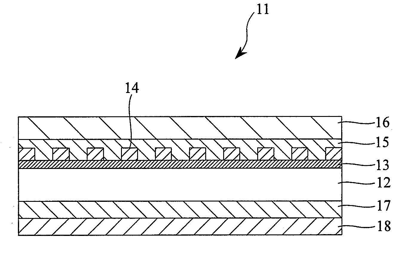
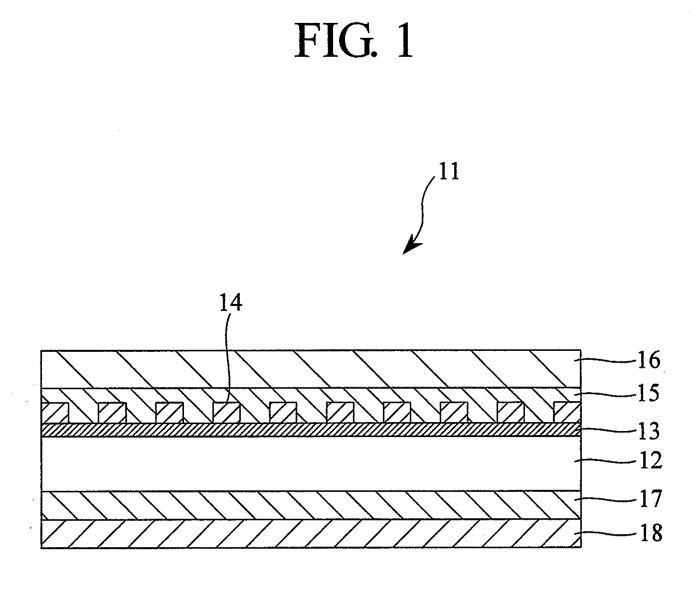
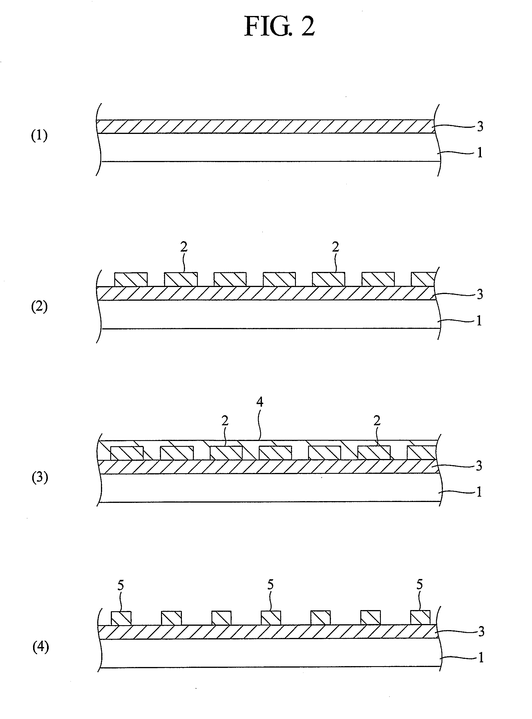
Image

Examples
example 1
Preparation of Optical Filter for Display
[0181](1) Formation of Intermediate Layer
[0182]A coating liquid for intermediate layer having the following formulation was applied onto a surface of a continuous polyethylene terephthalate (PET) film having thickness of 100 μm (width of 600 mm, length of 100 μm), dried and cured at 100° C. for three minutes to form an intermediate layer having a thickness of 80 nm. The resultant intermediate layer had refractive index of 1.65.
[0183]Formulation:
Polyester resin (Trade name: AD335-AE,50weight partsavailable from TOYO INK MFG. CO., LTD;40 wt. % of resin, 30 wt. % of toluene,30 wt. % of ethyl acetate)Polyisocyanate (Trade name: CAT-10L,5weight partsavailable from TOYO INK MFG. CO., LTD;52.5 wt. % of polyisocyanate,47.5 wt. % of MEK)Silicone (Trade name: KF96-20CS,0.03weight partavailable from Shin-Etsu Chemical Co., Ltd.;nonvolatile content;: 100 wt. %)ZrO2-methyl isobutyl ketone dispersing liquid75weight parts(Trade name: ZRMIBK 15 WT %-E02,avai...
example 2
[0193]Procedures of Example 1 were repeated except that an intermediate layer was formed by using the following formulation to prepare an optical filter for display.
[0194]Formulation:
Polyester resin (Trade name: TM-K55,50weight partsavailable from TOYO INK MFG. CO., LTD;30 wt. % of resin,70 wt. % of methyl ethyl ketone)Polyisocyanate (Trade name: CAT-10L,5weight partsavailable from TOYO INK MFG. CO., LTD;52.5 wt. % of polyisocyanate,47.5 wt. % of MEK)Silicone (Trade name: KF96-20CS,0.03weight partavailable from Shin-Etsu Chemical Co., Ltd.;nonvolatile content;: 100 wt. %)ZrO2-methyl isobutyl ketone dispersing liquid75weight parts(Trade name: ZRMIBK 15 WT %-E02,available from C. I. KASEI CO., LTD.,nonvolatile content: 15 wt. %)Cyclohexanone2000weight parts
example 3
[0200]Procedures of Example 1 were repeated except that the following layers were further provided to prepare an optical filter for display.
[0201](4) Formation of Near-Infrared Absorption Layer (Having Color Hue Adjusting Function)
[0202]The following composition:
Polymethyl methacrylate30weight partsTAP-20.4weight part(available from Yamada Chemical Co., Ltd.)Plast Red 83300.1weight part(available from Arimoto Chemical Co., Ltd.)CIR-10851.3weight part(available from Japan Carlit Co., Ltd.)IR-10A0.6weight part(available from Nippon Syokubai Co., Ltd.)Methyl ethyl ketone152weight partsMethyl isobutyl ketone18weight parts
was mixed to form a coating liquid, which was applied onto the reverse side of the PET film with a bar coater, and dried in an oven at 80° C. for five minutes. Hence, a near-infrared absorption layer provided with color hue adjusting function having thickness of 5 μm was formed on the reverse side of PET film.
[0203](5) Formation of Adhesive Layer
[0204]The following comp...
PUM
| Property | Measurement | Unit |
|---|---|---|
| contact angle | aaaaa | aaaaa |
| refractive index | aaaaa | aaaaa |
| refractive index | aaaaa | aaaaa |
Abstract
Description
Claims
Application Information