MQW Laser Structure Comprising Plural MQW Regions

a laser structure and mqw technology, applied in lasers, semiconductor lasers, laser details, etc., can solve the problems of difficult to grow an ingan heterostructure that has a sufficient content, significant design constraints on the laser, and cladding layer refractive index, and achieve the effect of promoting the propagation of emitted photons

Inactive Publication Date: 2010-06-17
THORLABS QUANTUM ELECTRONICS
View PDF11 Cites 23 Cited by
  • Summary
  • Abstract
  • Description
  • Claims
  • Application Information

AI Technical Summary

Benefits of technology

[0009]In accordance with another embodiment of the present disclosure, a multi-quantum well laser structure is provided where the active region comprises one or more active MQW regions configured for optically-pumped stimulated emission of photons. Each of the MQW regions comprises a plurality of quantum wells, which comprise a bandgap-reducing Group III nitride component, and intervening nitride barrier layers of barrier layer thickness a. Adjacent MQW regions are separated by a nitride spacer layer of spacer thickness b. The spacer thickness b is larger than the barrier layer thickness a. The bandgap of the quantum wells is lower than the bandgap of the intervening nitride barrier layers and the nitride spacer layer. The respective active, waveguide, and cladding regions form a multi-layered structure over the laser substrate such that the waveguide region guides the stimulated emission of photons from the active region, and the cladding region promotes propagation of the emitted photons in the waveguide region.

Problems solved by technology

Unfortunately, in the context of Group III nitride semiconductor lasers, the lattice-mismatch induced strain in the heterostructure and the thermal instability of InGaN place significant design constraints on the laser.
For example, it is challenging to grow an AlGaN cladding layer that is thick enough and has a high enough Al content to reduce cladding layer refractive index because AlGaN tensile strain generates cracking issues in the structure.
It is also difficult to grow an InGaN heterostructure that has a sufficient In content because of factors like high compressive strain, poor thermal stability, and difficulties in doping the material.
For example, where a contact metal is deposited on the top of the upper cladding layer of the laser structure, even slight mode tail penetration into the metal layer through the upper cladding layer can be a source of significant optical losses because absorption in the metal can be extremely high.

Method used


Image

  • MQW Laser Structure Comprising Plural MQW Regions
  • MQW Laser Structure Comprising Plural MQW Regions
  • MQW Laser Structure Comprising Plural MQW Regions

Examples


Embodiment Construction

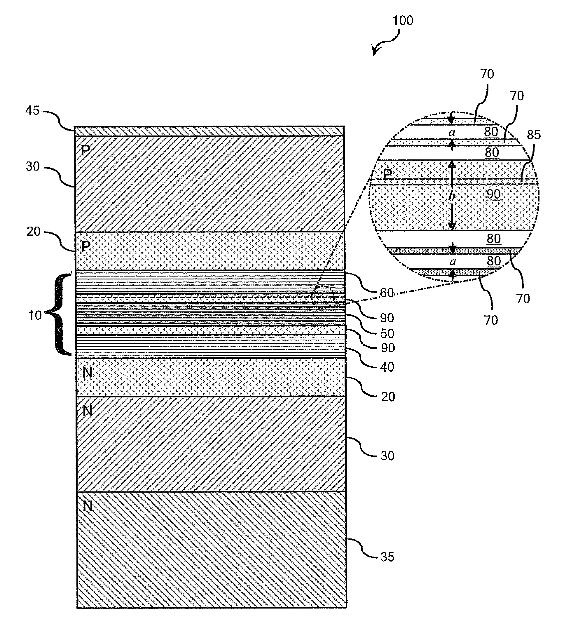
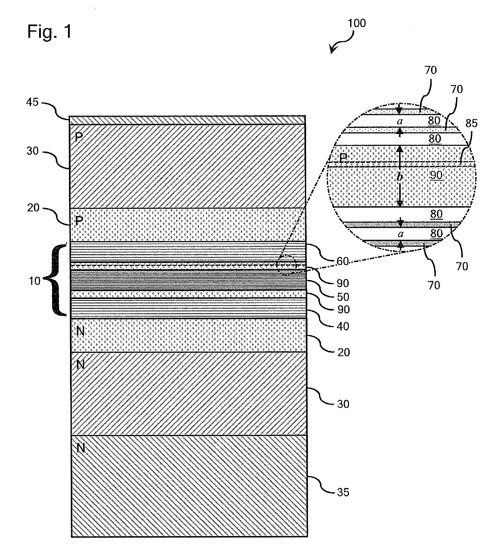
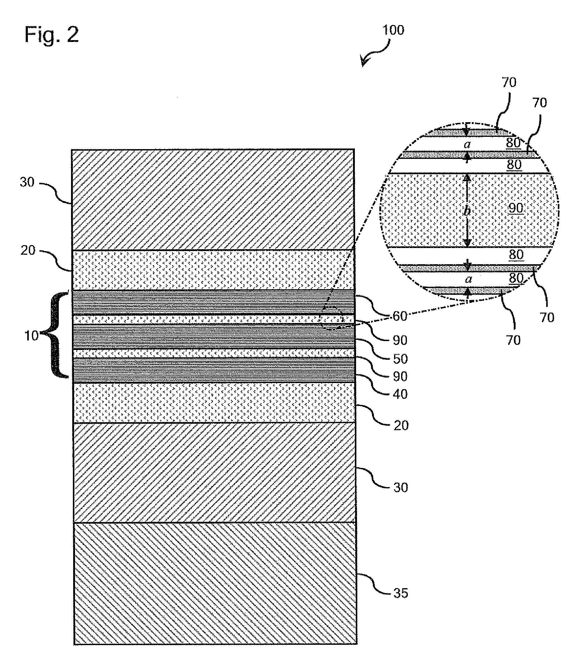
[0014]The multi-quantum well (MQW) laser structures 100 illustrated in FIGS. 1 and 2, comprise a semiconductor active region 10, a waveguide region comprising a pair of waveguide layers 20 disposed on opposite sides of the active region 10, and a cladding region comprising a pair of cladding layers 30 disposed on opposite sides of the waveguide region. The respective active, waveguide, and cladding regions are formed as a multi-layered structure over a laser substrate 35 such that the waveguide layers 20 of the waveguide region guide the stimulated emission of photons from the active region 10, and the cladding layers 30 of the cladding region promote propagation of the emitted photons in the waveguide region.

[0015]The active region 10 comprises a plurality of MQW regions 40, 50, 60, at least one of which is configured for stimulated emission of photons. The MQW regions 40, 50, 60 enhance optical confinement without introducing optical loss by providing a refractive index that is as...


PUM


Abstract

Multi-quantum well laser structures are provided comprising active and/or passive MQW regions. Each of the MQW regions comprises a plurality of quantum wells and intervening barrier layers. Adjacent MQW regions are separated by a spacer layer that is thicker than the intervening barrier layers. The bandgap of the quantum wells is lower than the bandgap of the intervening barrier layers and the spacer layer. The active region may comprise active and passive MQWs and be configured for electrically-pumped stimulated emission of photons or it may comprises active MQW regions configured for optically-pumped stimulated emission of photons.

Description

BACKGROUND[0001]1. Field[0002]The present disclosure relates to semiconductor lasers and, more particularly, to enhanced optical confinement in laser structures.[0003]2. Technical Background[0004]The present inventors have recognized that, to improve the optical confinement of light propagating in the waveguide of a semiconductor laser, confined mode out-coupling to the laser substrate should be reduced or eliminated. In addition, the optical field profile around the active region of the laser should be narrowed to ensure efficient overlap between the optical propagating mode and the gain region and to prevent optical loss due to optical mode penetration into metal contacts in the vicinity of the active region. These challenges are particularly acute for semiconductor lasers operating at wavelengths between approximately 450 nm and approximately 600 nm because such lasers are often prone to optical leakage.BRIEF SUMMARY[0005]Semiconductor lasers may comprise optical heterostructures...

Claims


Application Information

Patent Timeline
Patent Type & Authority Applications(United States)
IPC IPC(8): H01S5/30
CPCB82Y20/00H01S5/041H01S5/34333H01S5/2004H01S5/34H01S5/20
Inventor BHAT, RAJARAMNAPIERALA, JEROMESIZOV, DMITRYZAH, CHUNG-EN
Owner THORLABS QUANTUM ELECTRONICS
Why Eureka
Try Eureka