Time-of-flight mass spectrometer

a mass spectrometer and time-of-flight technology, applied in the field of time-of-flight mass spectrometers, can solve the problems of shifting the mass axis, the shift of the mass axis may possibly exceed the specified mass accuracy of the apparatus, and the shift etc., to achieve accurate estimation of the shift length of the mass axis of the mass spectrum, high mass accuracy, and high voltage

Inactive Publication Date: 2010-07-15
SHIMADZU CORP
View PDF2 Cites 15 Cited by
  • Summary
  • Abstract
  • Description
  • Claims
  • Application Information

AI Technical Summary

Benefits of technology

[0025]The time-of-flight mass spectrometer according to the present invention is capable of accurately estimating the shift length of the mass axis of a mass spectrum due to a change in the environmental temperature without directly measuring the temperature of the flight tube which is contained in a vacuum container and supplied with a high voltage. Thus, it is possible, for example, to obtain mass spectrums with high levels of mass accuracy.
[0026]To suppress the shift of the mass axis against changes in the environmental temperature, it has been conventionally necessary, for example, to select materials having a low coefficient of thermal expansion for the flight tube, use selected parts to reduce the temperature characteristics of the power unit, and provide the power unit with a temperature compensating circuit. Otherwise, it was necessary to take some other measures, such as containing the apparatus in a thermostatic bath capable of creating a controlled temperature condition that is barely affected by a sudden change in the environmental temperature. Any of these measures is very expensive and increases the price of the apparatus. Such hardware-based measures are less necessary (though not absolutely unnecessary) for the time-of-flight mass spectrometer according to the present invention since it can obtain highly accurate analysis results with reduced influence from the temperature by signal processing, or more specifically, by software-based techniques that can be executed on a computer. This allows the use of a simpler hardware system for temperature compensation, which is advantageous for the cost reduction of the apparatus.

Problems solved by technology

This leads to a variation in the time of flight of the ions having the same mass, which causes a shift of the mass axis of the mass spectrum.
If the temperature change of the flight tube is large, the aforementioned shift of the mass axis may possibly exceed the specified mass accuracy of the apparatus.
However, even if the temperature of the vacuum chamber is controlled, the temperature control of the vacuum chamber may be disordered by a sudden change in the ambient temperature or other factors, which can consequently cause a shift of the mass axis.
However, it is difficult to attach a temperature sensor to the flight tube to directly monitor its temperature, because flight tubes are generally used as an accelerating electrode for initially accelerating the ions and hence need to be supplied with a high voltage of several kV or higher and placed in a vacuum atmosphere within a vacuum chamber.
However, it is inevitable that the actual temperature change of the flight tube has a relatively large response delay from the monitored temperature of the vacuum chamber since the heat capacity of the flight tube is generally large and the thermal conductivity of the vacuum atmosphere is intrinsically low.
If the shift length of the mass axis is determined on the assumption that the value monitored with the temperature sensor attached to the vacuum chamber equals the temperature of the flight tube, the determination result may be erroneous.
Conversely, an actually correct analysis result may be mistaken for a poorly accurate one and discarded.
However, the required level of mass accuracy varies depending on the purpose of the analysis and other factors; it is in some cases necessary to achieve higher levels of mass accuracy that cannot be achieved by the mass axis correction based on the previously described estimating operation.

Method used


Image

  • Time-of-flight mass spectrometer
  • Time-of-flight mass spectrometer
  • Time-of-flight mass spectrometer

Examples


Embodiment Construction

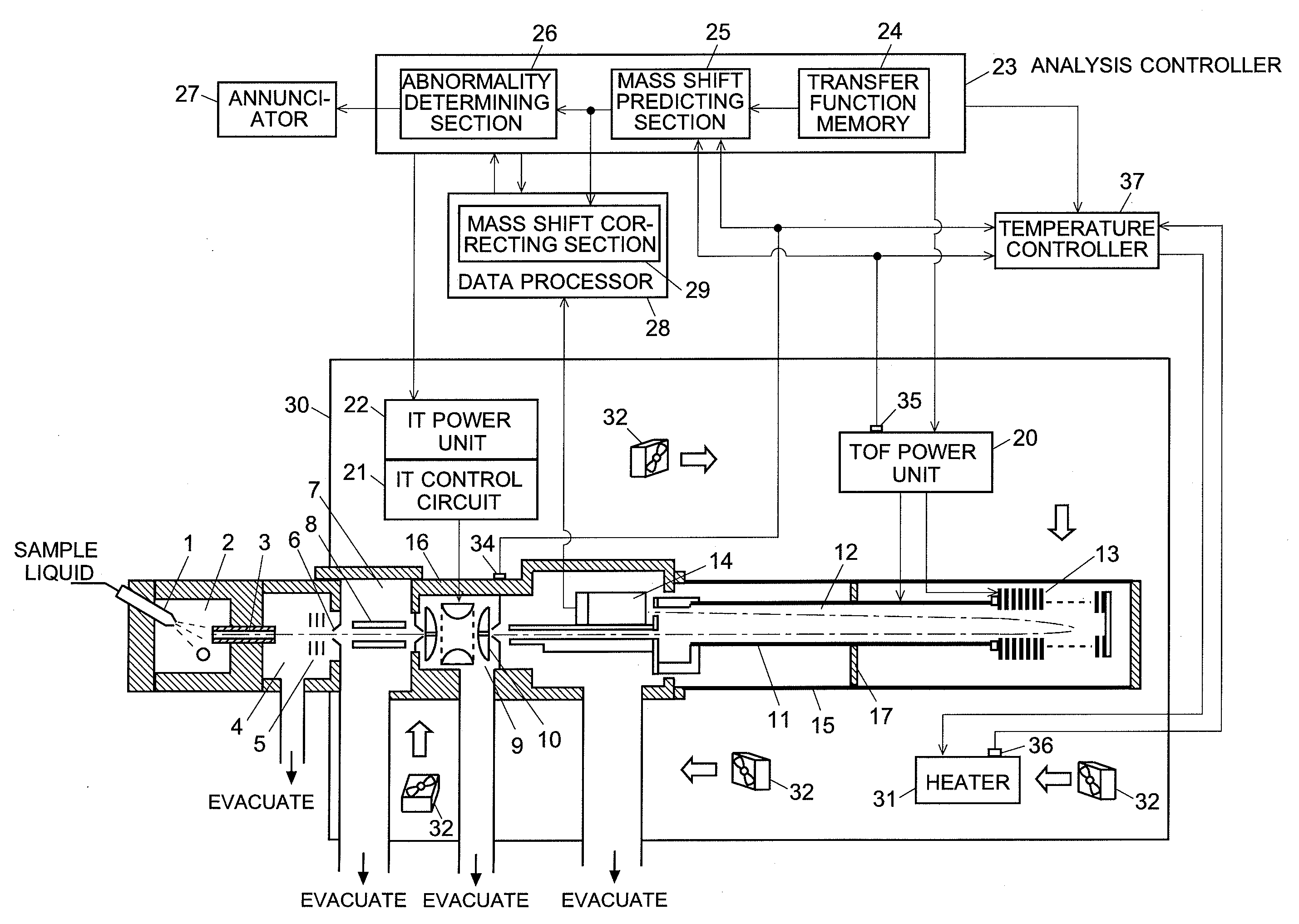
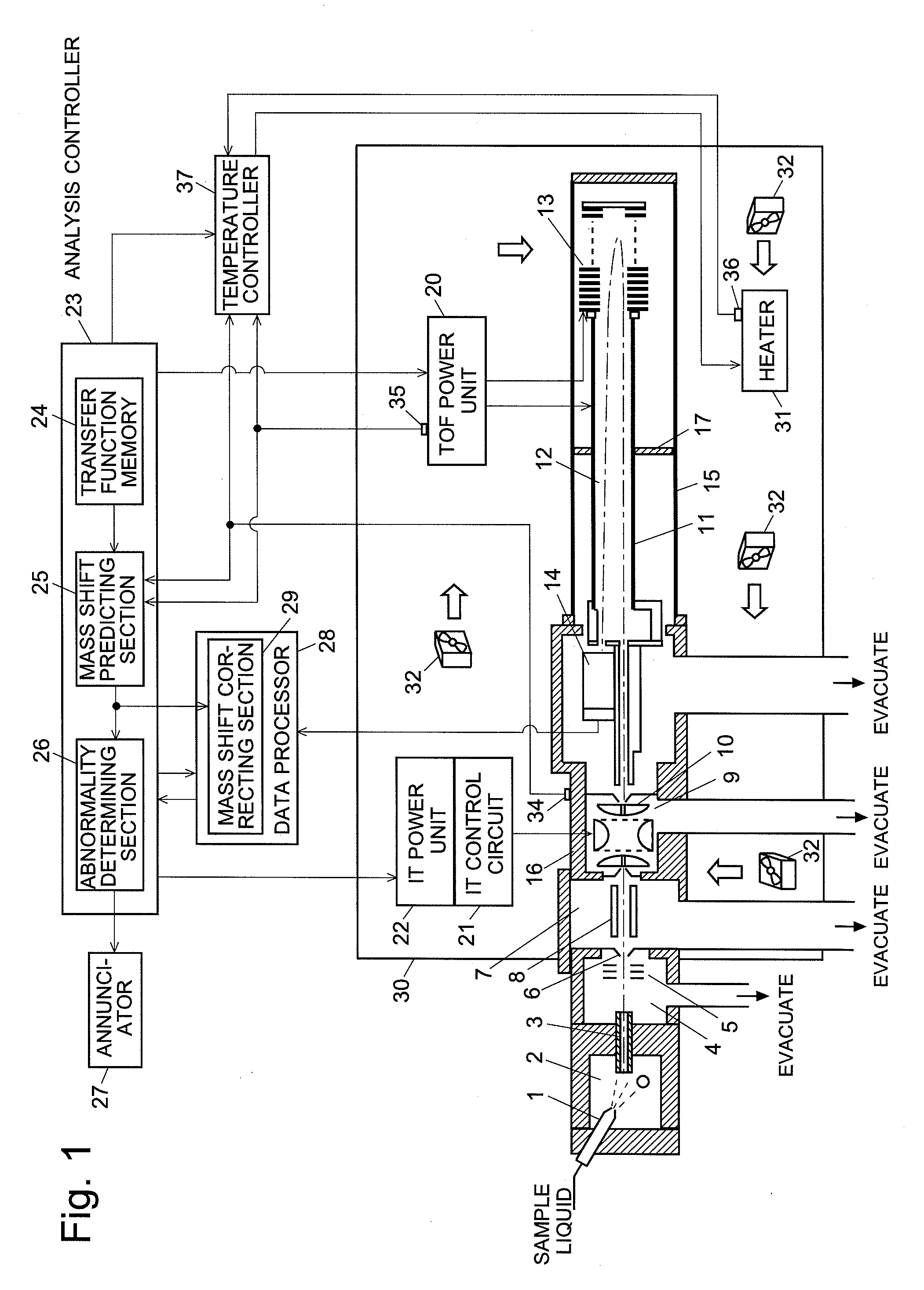
[0065]A TOFMS, which is an embodiment of the present invention, is hereinafter described with reference to the attached drawings. FIG. 1 is a configuration diagram showing the main components of the TOFMS according to the present embodiment. This TOFMS includes an atmospheric pressure ionization source, an ion trap and a time-of-flight mass analyzer. It can be used, for example, in a liquid chromatograph mass spectrometer (LC / MS) in which a liquid chromatograph connected in the preceding stage.

[0066]A sample liquid containing a target component is sprayed from an electrospray nozzle 1 into an ionization chamber 2 at an approximately atmospheric pressure, whereby ions are produced from the objective component. The resulting ions are sent through a heating pipe 3 into a first intermediate vacuum chamber 4, which is evacuated to a low vacuum state by a rotary pump (not shown). Within the first intermediate vacuum chamber 4, the ions are focused by a first ion lens 5 and sent through a ...


PUM


Abstract

A shift of mass axis that occurs when the temperature of a vacuum container consisting of a vacuum chamber (15) and IT block (16) or that of a TOF power unit (20) for applying an ion acceleration voltage is changed, is respectively measured beforehand, and parameters expressing a transfer function based on its response are stored in a transfer function memory (24). During an analysis, a mass shift predicting operation section (25) estimates the current shift length of the mass axis from the current temperatures of the IT block (16) and TOF power unit (20) obtained by first and second temperature sensors (34 and 35) as well as from the two transfer functions stored in the memory (24). A mass shift correcting section (29) corrects the mass axis of the mass spectrum according to the estimated shift length. Thus, if the ambient temperature suddenly changes, the shift of the mass axis of the mass spectrum due to the temperature change is corrected with high accuracy, so that a mass spectrum with a high level of mass accuracy can be created.

Description

TECHNICAL FIELD[0001]The present invention relates to a time-of-flight mass spectrometer (TOFMS).BACKGROUND ART[0002]In a time-of-flight mass spectrometer (which is hereinafter abbreviated to TOFMS), various ions that have been almost simultaneously accelerated by an electric field are introduced into a flight space formed within a flight tube. Those ions are subsequently separated into different kinds of ions having different masses (or m / z, to be exact) according to their time of flight, i.e. the time required for each ion to travel through the flight space until it reaches the detector. The detector continuously produces detection signals corresponding to the amount of the incoming ions. Therefore, after converting the time-of-flight to the mass, it is possible to create a mass spectrum with the abscissa axis as the mass axis and the coordinate axis as the signal intensity axis.[0003]In the TOFMS, the flight distance of the ions can slightly change due to a mechanical expansion o...

Claims


Application Information

Patent Timeline
Patent Type & Authority Applications(United States)
IPC IPC(8): H01J49/40
CPCG01N27/62H01J49/40H01J49/0009
Inventor YAMAUCHI, KAZUOOKADO, TAKAO
Owner SHIMADZU CORP
Why Eureka
Try Eureka