Beam Detector and Beam Monitor Using The Same

Inactive Publication Date: 2010-09-02
KOBE STEEL LTD
View PDF9 Cites 9 Cited by
  • Summary
  • Abstract
  • Description
  • Claims
  • Application Information

AI Technical Summary

Benefits of technology

[0037]Since the beam detector of the present invention includes a beam irradiation portion, which is formed using at least a polycrystalline diamond film, for detecting the position and intensity of beams, and this polycrystalline diamond film is a polycrystalline diamond (C) film containing at least one element (X) selected from the group consisting of silicon (Si), nitrogen (N), lithium (Li), beryllium (Be), boron (B), phosphorus (P), sulfur (S), nickel (Ni), and vanadium (V) at an X/C of 0.1 to 1,000 ppm, when the beams are irradiated to this diamond film, a light emission function of emitting light is imparted thereto: hence, monochromatic light, such as visible light or ultraviolet light, having sufficient intensity can be obtained from a beam irradiation spot.
[0038]Visible light excited inside the diamond film is emitted outside the film while being scattered by minute crystalline grain boundaries present inside the polycrystalline diamond film. Hence, precisely speaking, the beam diameter is detected larger than the actual beam diameter by the order of micrometers due to the spread of the beams. However, in practice, the spread on the order of micrometers will cause no problems. On the other hand, when the diamond film is formed of a single crystal, since grain boundaries are not present in the film, internal scattering does not occur; however, excited visible light is reflected on the film surface and is then extracted outside the film from an edge portion of a sample. As a result, a beam spot is not observed, and hence the single crystal cannot be used for the beam position detection.
[0

Problems solved by technology

Since these beams cannot be recognized by the naked eye, it is not easy to precisely detect the position of the beams as described above, and hence the adjustment of an optical system is difficult.
In addition, since energy of synchrotron radiation is high, dangerous accidents may occur in some cases such that an object not to be irradiated or an experimenter is irrdiated with high energy light by mistake, or such that an experimenter is unconsciously and indirectly irradiated with a large amount of x rays.
In general, since the energy of synchrotron radiation is high, a fluorescent plate itself, which is used to observe the position or the like of electron beams, is damaged thereby; hence, it cannot be used for the purpose described above.
However, the above x-ray beam monitor according to the conventional example can estimate the one-dimensional central position (for example, along the x coordinate) but cannot determine a two-dimensional position (along the y coordinate).
However, by the structure as described above, since radiation beams pass through the above monitors twice, absorption and scattering of the beams occur, and hence the quality of the beams are disadvantageously degraded.
In addition, signals generated by emitted electrons interfere with each other, and

Method used


Image

  • Beam Detector and Beam Monitor Using The Same
  • Beam Detector and Beam Monitor Using The Same
  • Beam Detector and Beam Monitor Using The Same

Examples


example 1

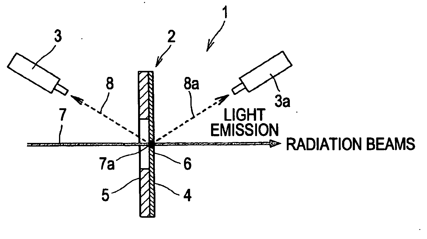
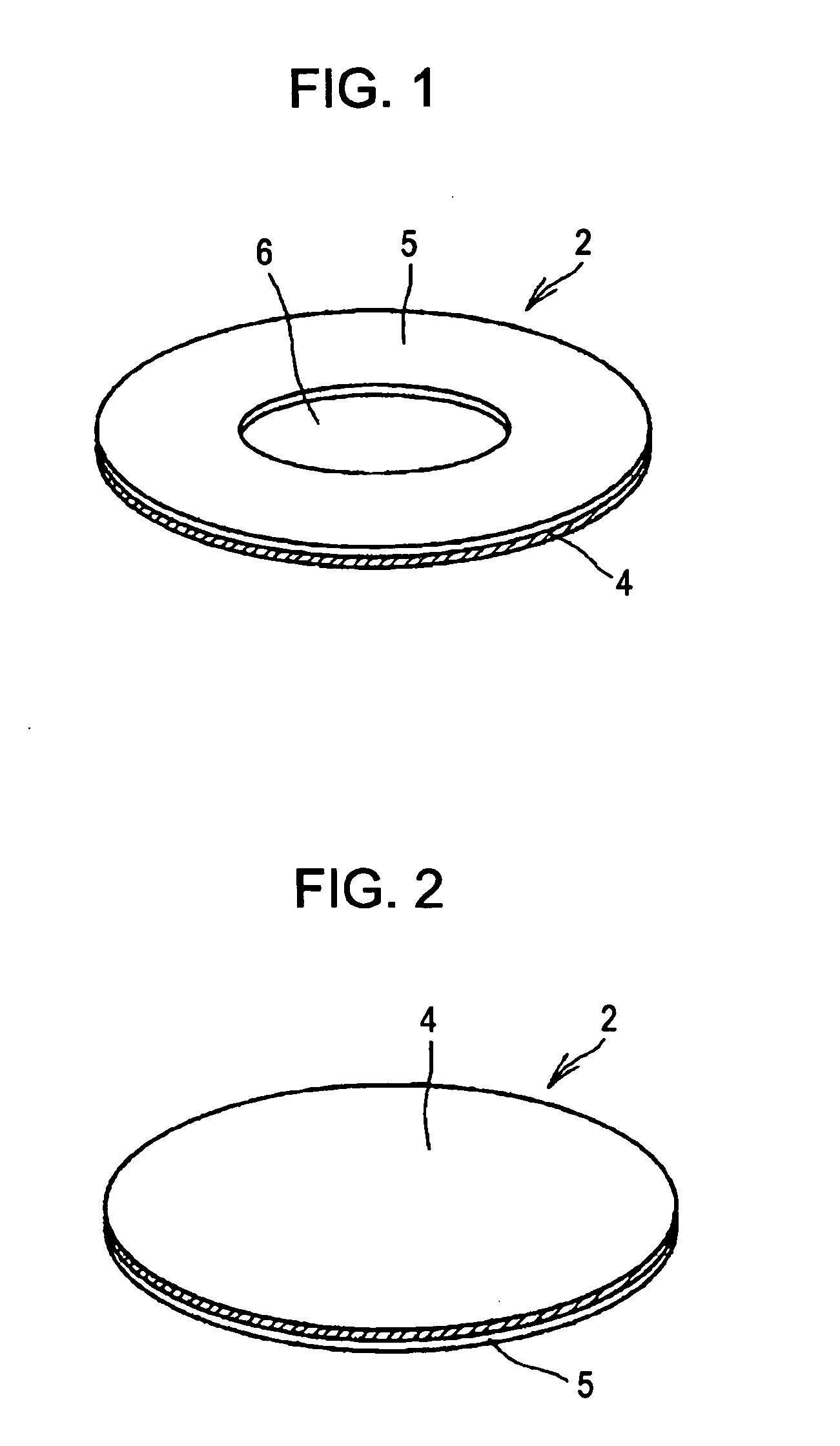
[0096]By the following process, the beam detector 2 shown in FIGS. 1 and 2 was formed. First, ultrasonic waves were applied on a silicon substrate having a diameter of 1 inch in an ethanol suspension containing a diamond powder having a diameter of several tens of micrometers, so that a treatment for promoting nuclear generation was performed. After diamond powder adhering on the substrate was washed out, the silicon substrate was placed in a microwave plasma CVD apparatus, so that a diamond film was formed. As a staring gas, a mixed gas containing 1 percent by volume of methane and 99 percent by volume of hydrogen was used. The gas pressure was set to 45 Torr and the substrate temperature was set to 800° C.

[0097]In order to incorporating Si in the polycrystalline diamond film, silane (SiH4) or disilane (Si2H6) diluted with hydrogen was further added to the starting gas, or a silicon wafer piece was disposed beside the silicon substrate. As a result, by film formation performed for ...

example 2

[0100]By a process similar to that in Example 1, diamond doped with boron was formed. In order to dope boron in a polycrystalline diamond film, diborane (B2H6) or trimethylboron (B(CH3)3) diluted with hydrogen was further added to the starting gas, or a piece of boric acid (B2O3) was disposed beside the silicon substrate. As a result, by film formation performed for 20 to 75 hours, a polycrystalline diamond film having a thickness of 15 to 48 μm was obtained. It was confirmed that boron atoms were incorporated in the film at a concentration of 1 to 100 ppm.

[0101]From the boron-doped diamond sample as described above, by a method similar to that in Example 1, part of the silicon substrate was processed by an etching treatment, so that a beam detector was formed. When the beam detector thus formed was irradiated with x-ray beams having an energy of 15 keV, from the polycrystalline diamond film at the irradiation spot, blue-green light emission was observed. In addition, when observati...

example 3

[0102]In a manner similar to that of Example 1, polycrystalline diamond films were formed by incorporating Si, N, Li, Be, B, P and in polycrystalline diamond films each forming a beam detector. When these elements were incorporated in the polycrystalline diamond films, it was confirmed that the light emission of visible light to ultraviolet light was performed from the irradiation spot by the energy of synchrotron radiation. However, as shown in Table 1, the light emission spectra were significantly different from each other by the types of addition elements and the concentrations thereof.

TABLE 1AdditionMethod for Adding ElementLight EmissionElementto Diamond FilmWavelength (nm)SiSiH4 or Si2H6 is added516-539, 738to starting gas.NN2 or NH3 is added to starting gas.389, 415, 516-539, 575LiLi ions are implanted.438BeMetal Be is disposed on a substrate516-539supporting table.BB2H6 is added to starting gas.443, 516-539PPH3 is added to starting gas.230, 516-539SH2S is added to starting g...


PUM

PropertyMeasurementUnit
Fractionaaaaaaaaaa
Thicknessaaaaaaaaaa
Thicknessaaaaaaaaaa

Abstract

A beam detector and a beam monitor using the same are provided, the beam detector being capable of precisely and stably detecting, for a long period of time, the position, the intensity distribution, and the change with time of radiation beams, soft x-ray beams, and the like and being manufactured at a low cost as compared to that of a conventional detection device.
In a beam detector 2 for detecting the position and intensity of beams, a beam irradiation portion 6 to be irradiated with beams 7 is formed of a polycrystalline diamond (C) film 4 containing at least one element (X) selected from the group consisting of silicon (Si), nitrogen (N), lithium (Li), beryllium (Be), boron (B), phosphorus (P), sulfur (S), nickel (Ni), and vanadium (V) at an X/C of 0.1 to 1,000 ppm, and this polycrystalline diamond film 4 has a light emission function of performing light emissions 8 and 8a when it is irradiated with the beams 7. By the beam detector 2 as described above and light emission observation means 3 and 3a for observing the above light emission phenomenon, a beam monitor 1 is formed.

Description

TECHNICAL FIELD[0001]The present invention relates to a beam detector for detecting the position, intensity, and the like of beam light by irradiating a beam irradiation portion with the beams, such as high-energy synchrotron radiation, generated by a synchrotron radiation facility or the like and to a beam monitor using the above beam detector.BACKGROUND ART[0002]In recent years, in research and development in the fields of medical care, materials, electronics, and the like, synchrotron radiation facilities and the like, which generate ultraviolet beams to x-ray beams, have been widely utilized. Since these beams cannot be recognized by the naked eye, it is not easy to precisely detect the position of the beams as described above, and hence the adjustment of an optical system is difficult.[0003]In addition, since energy of synchrotron radiation is high, dangerous accidents may occur in some cases such that an object not to be irradiated or an experimenter is irrdiated with high ene...

Claims


Application Information

Patent Timeline
IPC IPC(8): G01T1/202C09K11/65
CPCC23C16/0254G01T1/29C23C16/277C23C16/274
Inventor KOBASHI, KOJITACHIBANA, TAKESHIYOKOTA, YOSHIHIROHAYASHI, KAZUSHI
Owner KOBE STEEL LTD
Why Eureka
Try Eureka