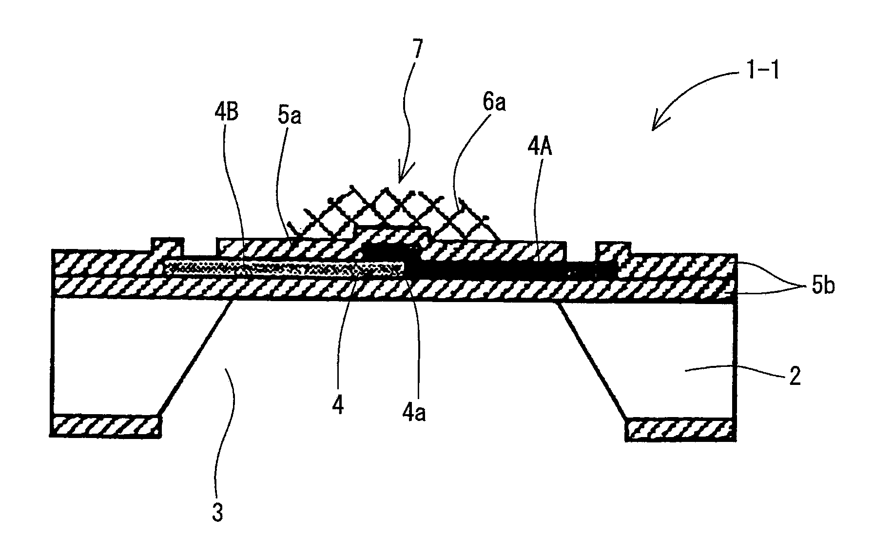
[0012]With the combustible gas sensor according to the invention recited in claim 1 having a characteristic construction such as described above, when the measurement object gas is brought into contact with the
porous catalyst layer or the chain-form catalyst layer, the combustible gas contained in the measurement object gas generates a reaction heat by being oxidized with the oxidation catalyst particles carried on the porous catalyst layer or the chain-form oxidation catalyst particles forming the chain-form catalyst layer. For example, when the combustible gas is a hydrogen gas (H2), as shown by the reaction formula:2H2+O2→2H2O+Q (1),the hydrogen gas (H2) molecules react with the
oxygen gas (O2) molecules to generate water molecules (H2O) and, at this time, a reaction heat Q is generated. This reaction heat is efficiently transferred to the heat-sensitive part of the temperature measurement element by passing from the surface of the oxidation catalyst particles through the
porous layer or directly from the surface of the chain-form oxidation catalyst layer particles, whereby the heat-sensitive part will have a
raised temperature. Here, because the oxidation catalyst particles are carried on the
porous layer or the oxidation catalyst particles are linked and bonded in a chain form, a sufficiently large contact area between the combustible gas contained in the measurement object gas and the oxidation catalyst particles can be attained, so that the amount of
heat generation Q by the above reaction formula (1) is extremely large, and the degree of temperature rise of the heat-sensitive part of the temperature measurement element can be enhanced. Therefore, by using a porous catalyst layer carrying oxidation catalyst particles or a chain-form catalyst layer having oxidation catalyst particles linked and bonded in a chain form, the efficiency of temperature rise at the heat-sensitive part of the temperature measurement element can be enhanced while reducing the scale of the gas sensor as a whole. This produces an effect such that a considerable improvement in the concentration measurement sensitivity and
measurement precision can be realized even with a combustible gas of low concentration such as hydrogen contained in the measurement object gas.
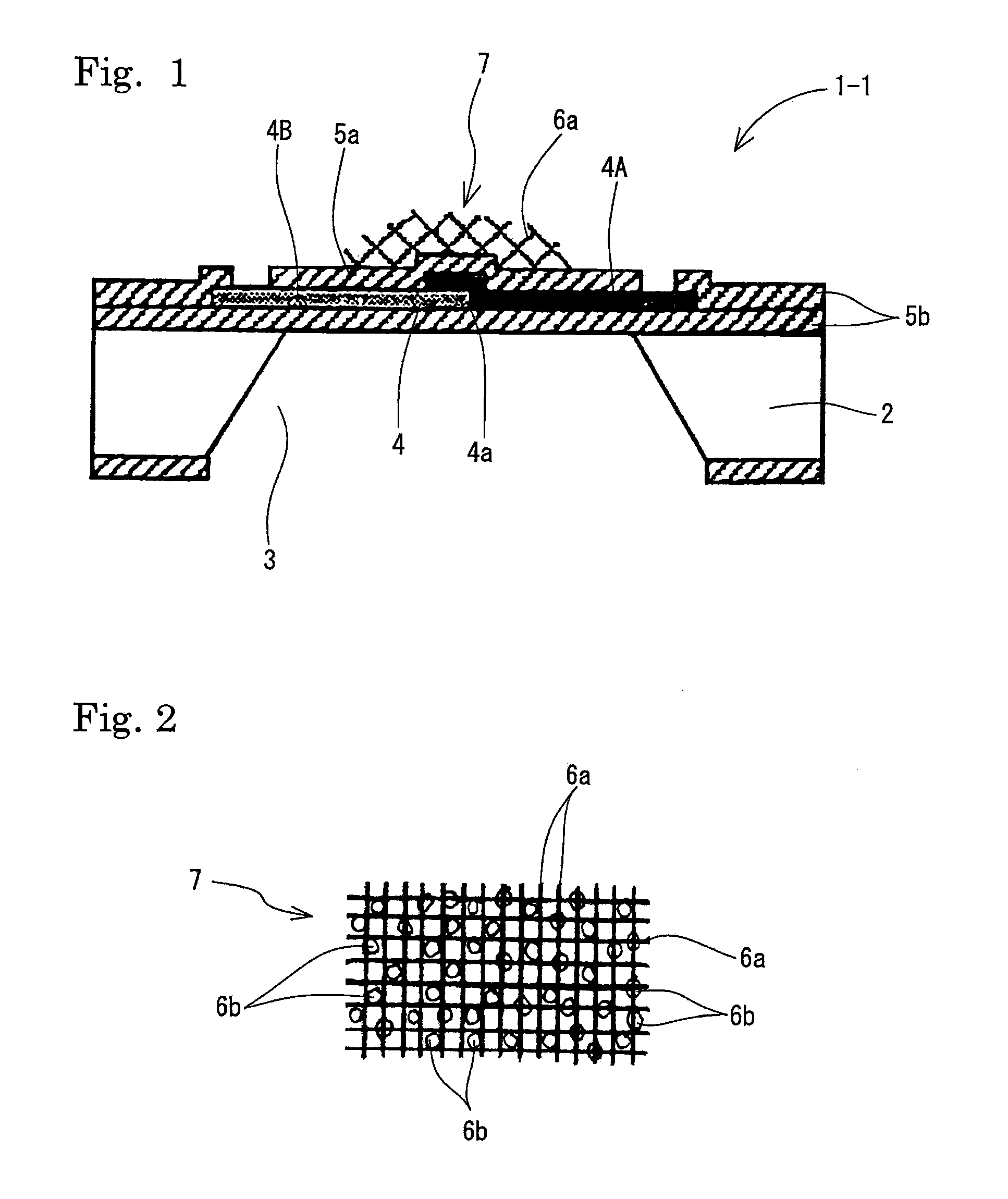
[0013]The porous catalyst layer in the combustible gas sensor according to the invention of claim 1 may be one formed by allowing a porous material selected from layer-form fibers,
porous ceramics, and fibrous or cluster-form carbon nanotubes to carry oxidation catalyst particles selected from noble metals including
platinum,
palladium,
rhodium,
iridium,
nickel, and
ruthenium (claim 2). In particular, in the case of using, as the porous catalyst layer, those formed by bonding oxidation catalyst particles with a cluster-form
carbon nanotube formed by growing on a plurality of nuclei that are agglomerated by heat treatment of a
nickel thin film layer, an iron thin film layer, or a
cobalt thin film layer (claim 3), the contact area with the measurement object gas can be ensured to be large; the
bonding strength of the porous catalyst layer to the heat-sensitive part of the temperature measurement element can be enhanced to be tough; and the heat transference (speed, efficiency) of the oxidation reaction heat to the heat-sensitive part will be excellent, thereby achieving a further improvement in the measurement sensitivity.
[0014]Also, as the chain-form catalyst layer in the combustible gas sensor according to the invention of claim 1, those that are formed to have a porous form by linking and bonding oxidation catalyst particles with each other in a chain form by dispersing numerous oxidation catalyst particles with use of a dispersing agent and performing a heat treatment can be used (claim 4). In this case, the measurement object gas can be directly brought into contact with the chain-form oxidation catalyst particles, whereby the oxidation reaction heat quantity can be increased and the predetermined measurement sensitivity and
measurement precision can be further improved.
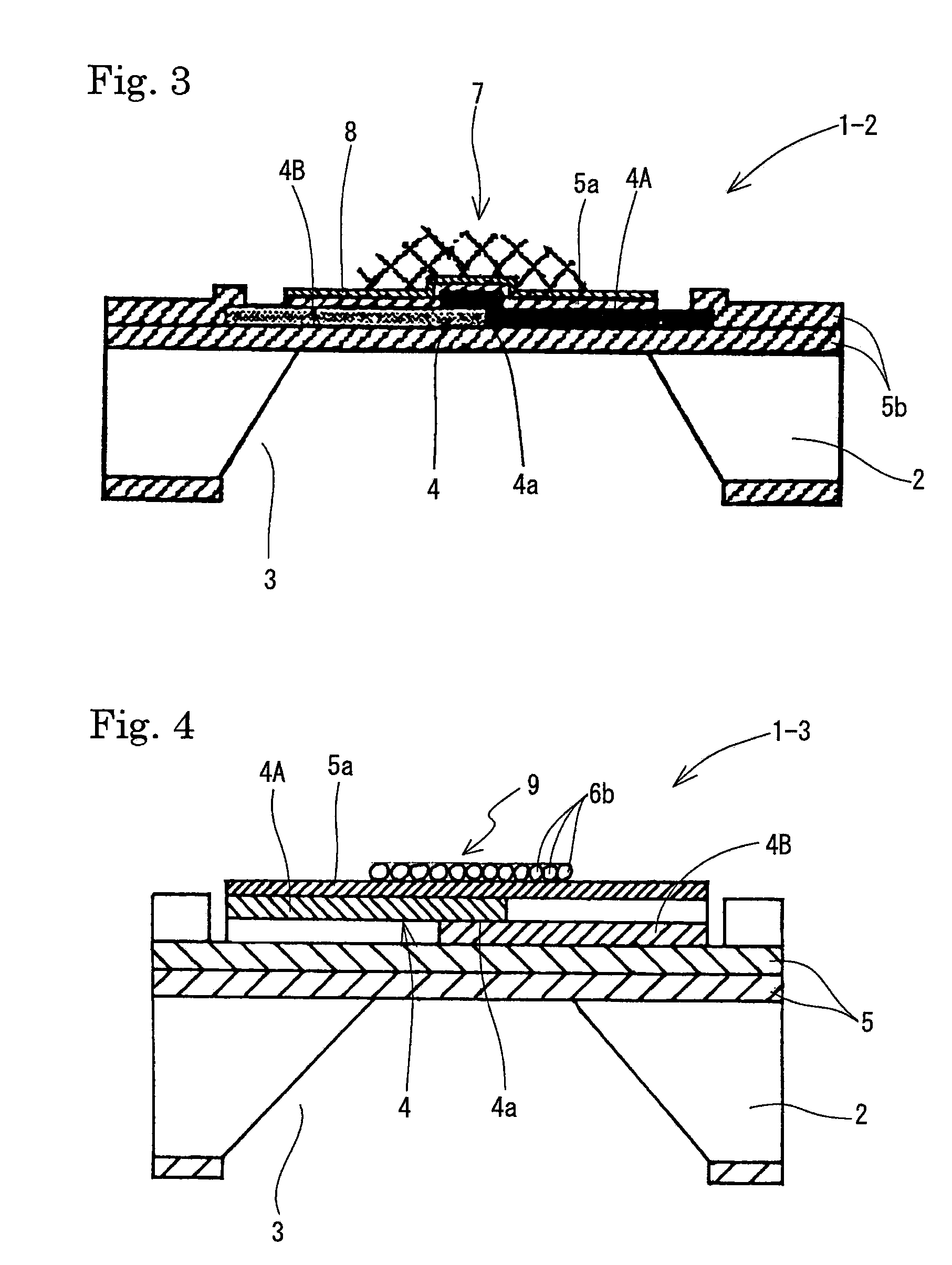
[0015]Also, as the temperature measurement element in the combustible gas sensor according to the invention of claim 1, use of a
thermopile is preferable (claim 5). Further, in the combustible gas sensor according to the invention of either of claims 1 through 5, the porous catalyst layer carrying the oxidation catalyst particles or the chain-form catalyst layer may be formed on a back surface of the heat-sensitive part of the temperature measurement element (claim 6). In this case, even if there is some
position shift in forming the porous catalyst layer or the chain-form catalyst layer on the heat-sensitive part of the temperature measurement element, the catalyst layer is not brought into contact with the cold contact point part of the temperature measurement element in structure, and there is no sensitivity decrease accompanying the unnecessary temperature rise of the cold contact point part. As a result thereof, an improvement in the measurement sensitivity and the measurement precision can be achieved, and an effect of facilitating the
mass production of combustible gas sensors having uniform characteristics is provided.
[0016]On the other hand, a combustible gas sensor according to the invention recited in claim 7 devised in order to achieve the aforementioned other object is a combustible gas sensor constructed in such a manner that the concentration of a combustible gas contained in a measurement object gas is measured by sensing the amount of heat generation of the measurement object gas with a temperature measurement element that is mounted on a
semiconductor substrate surface, characterized in that at least
two temperature measurement elements are mounted to be close to each other on the
semiconductor substrate surface, and the temperature measurement elements are divided into those in which a porous catalyst layer made by allowing a porous material to carry oxidation catalyst particles that generate oxidation reaction heat by contact with the measurement object gas or a chain-form catalyst layer made by linking and bonding numerous oxidation catalyst particles in a chain form is provided on a heat-sensitive part and those in which the porous catalyst layer or the chain-form catalyst layer is not provided on the heat-sensitive part.
[0017]Also, a combustible gas sensor according to the invention recited in claim 8 devised in order to achieve the same object as the invention recited in claim 7 is a combustible gas sensor constructed in such a manner that the concentration of a combustible gas contained in a measurement object gas is measured by sensing the amount of heat generation of the measurement object gas with a temperature measurement element that is mounted on a
semiconductor substrate surface, characterized in that one temperature measurement element having at least two heat-sensitive parts is mounted on the semiconductor substrate surface, and the heat-sensitive parts in the temperature measurement element are divided into those in which a porous catalyst layer made by allowing a porous material to carry oxidation catalyst particles that generate oxidation reaction heat by contact with the measurement object gas or a chain-form catalyst layer made by linking and bonding numerous oxidation catalyst particles in a chain form is provided and those in which the porous catalyst layer or the chain-form catalyst layer is not provided.

