Hearing aid and a method of operating a hearing aid

a hearing aid and battery technology, applied in the field of hearing aids, can solve the problems of limiting the durability of mechanical switches and battery terminals within the hearing aid, affecting the operation of hearing aids, so as to save the power consumed by this part of the circuit, and effectively inhibit the operation.

Active Publication Date: 2010-09-30
WIDEX AS
View PDF9 Cites 32 Cited by
  • Summary
  • Abstract
  • Description
  • Claims
  • Application Information

AI Technical Summary

Benefits of technology

[0034]These semiconductor elements, which may be compared to tiny voltage controlled switches, have the property of drawing very little current when being in one of these states, but they draw a comparatively large amount of current when switching from one state to another. A clock generator usually caters for the timing of the switching of the semiconductor elements together performing the operations of the digital hearing aid circuit. The clock generator is thus potentially controlling the switching of many of the semiconductor elements several millions of times per second.
[0035]Every time one semiconductor element switches from one state to another, current is drawn from the battery cell, and if some of the semiconductor elements are connected in such a way as to retain the same state over time, this portion of the semiconductor elements does not draw any significant current when compared to the rest of the semiconductor elements in the circuit. As the clock generator controls the switching of the semiconductor elements in a digital hearing aid circuit, means for temporarily disabling the clock signal otherwise fed to a dedicated part of the circuit will effectively inhibit the operations in this dedicated part of the circuit, thus saving the power consumed by this part of the circuit.

Problems solved by technology

Both mechanical switches and battery terminals in hearing aids are prone to wear when the hearing aid is turned on and off many times. Battery terminals and contact elements of switches are preferably made from spring steel or phosphor bronze bent into the desired shape and subsequently gold-plated in order to prevent corrosion, but the physical dimensions of the hearing aid severely limit the obtainable durability of mechanical switches and battery terminals within the hearing aid, and the double duty performed by the battery compartment assembly, i.e. when changing the battery cell and when powering the hearing aid on and off puts a considerable amount of stress upon the battery terminals.
This type of circuit has a prolonged service life when compared to similarly employed mechanical switches, but it draws a modest amount of leakage current while the device is switched off.
Apart from being prone to wear and breakage, tiny mechanical switches may also be difficult to operate properly, e.g. by physically disabled hearing aid users.
Power switches operated by dislocating the battery cell from the battery terminals of the hearing aid may also result in the cell falling out of the battery compartment by accident and eventually getting lost as the result of an erroneous operation by the user.
An active command for controlling the power in a hearing aid from a remote control device is not easily employed.
Obviously, if all circuitry in the hearing aid is powered off, no means for powering the hearing aid back on again by a corresponding command from the remote control device would have any effect.
A part of the hearing aid is thus being disabled whenever the hearing aid is placed in its storage box.
The range of a secure detection of the presence of a passive resonant circuit is limited by the amount of energy the transmitter is capable of dissipating.
This puts a serious constraint to the detection range of the system, as the energy transmitted follows the inverse square law, i.e. the electromagnetic energy dissipated by the transceiver coil and the energy reflected back to the transceiver coil by the passive circuit decreases with the distance squared.
When the transmitter in the hearing aid has to operate continuously in order to detect the presence of the passive resonant circuit, a considerable amount of current is consumed by the hearing aid even when it is supposed to be powered off.
Acoustical transmission usually involves ultrasonic transducers unsuitable for use in a hearing aid due to limitations in size and power requirements.
Optical transmission usually involves low-power infrared light emitting diodes, but such designs are dependent of a clear line-of-sight between the transmitter and the receiver, difficult to obtain in hearing aids being worn behind or in a user's ear.

Method used


Image

  • Hearing aid and a method of operating a hearing aid
  • Hearing aid and a method of operating a hearing aid
  • Hearing aid and a method of operating a hearing aid

Examples


Embodiment Construction

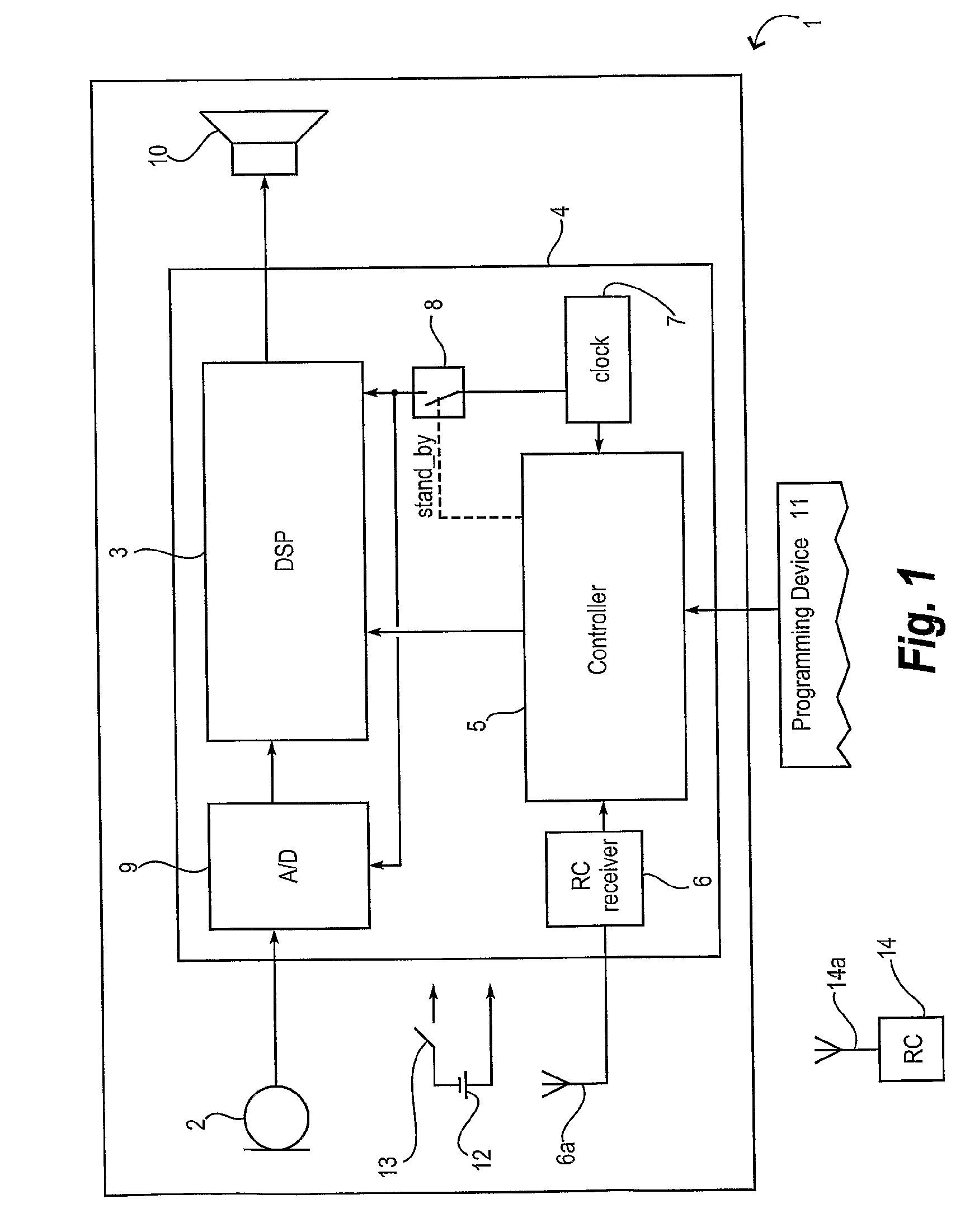
[0041]FIG. 1 is a schematic block diagram illustrating a hearing aid 1 comprising a microphone 2, an output transducer 10, a microelectronic circuit 4 comprising an A / D converter 9, a signal processor 3, a controller 5, a remote control receiver 6, a clock generator 7, and an electrically controlled switch 8. The hearing aid 1 further comprises a power source 12, preferably in the form of a battery cell, a mechanically operated battery switch 13, and a receiver antenna 6a. Also illustrated in FIG. 1 is a remote control transmitter 14 having a transmitter antenna 14a, and an external programming device 11.

[0042]When in use, the microphone 2 picks up acoustic signals and converts them into analog electrical signals. The analog electrical signals are converted into digital signals by the A / D converter 9 to make them available for conditioning and amplification by the signal processor 3 according to a compensating prescription in order to alleviate a hearing loss. The signal processor 3...


PUM


Abstract

A hearing aid (1) has means for entering or leaving a stand-by mode initiated by a remote control (14). During use, a dedicated stand-by command issued by the remote control is received and decoded in the hearing aid. When a stand-by command is recognized, a clock signal to the signal-processing parts (3) of the hearing aid (1) is disabled, effectively halting the signal processing. In the stand-by mode, the hearing aid circuitry draws very little power from the battery. Reception of a similar command in the hearing aid during the stand-by mode enables the clock signal to the signal-processing parts of the hearing aid, enabling signal processing. A method to manage the stand-by mode involves the step of calling a soft-boot routine when the hearing aid leaves stand-by mode and resumes normal operation.

Description

RELATED APPLICATIONS[0001]The present application is a continuation-in-part of application No. PCT / DK 2007000552, filed on Dec. 19, 2007, in Denmark and published as WO2009076949 A1.BACKGROUND OF THE INVENTION[0002]1. Field of the Invention[0003]The present application relates to hearing aids. More specifically, it relates to battery powered hearing aids comprising remote control receivers. The invention further relates to a method of operating a hearing aid. The invention also relates to a hearing aid system comprising a hearing aid and a remote control.[0004]Present-day hearing aids are powered by tiny battery cells, preferably of the zinc-air variety. Zinc-air battery cells comprise a zinc anode, an aqueous alkaline electrolyte and an air cathode. Power is derived from the chemical reduction of oxygen, derived from the surrounding air, at the cathode, and the oxidation of zinc at the anode. Such a cell has the advantages of a very high power density, a comparatively constant powe...

Claims


Application Information

Patent Timeline
Patent Type & Authority Applications(United States)
IPC IPC(8): H04R25/00
CPCH04R2460/03H04R25/558
Inventor SUURBALLE, MORTEN
Owner WIDEX AS
Why Eureka
Try Eureka