
Article and a method of surface treatment of an article

a surface treatment and article technology, applied in the field of coatings on articles, can solve the problem of unlikely harm to the therapeutic agent by temperatur

Inactive Publication Date: 2010-09-30
UCL BUSINESS PLC
View PDF5 Cites 7 Cited by
  • Summary
  • Abstract
  • Description
  • Claims
  • Application Information

AI Technical Summary

Benefits of technology

The present invention provides a method for surface treatment of an implant by electrochemical deposition of a layer containing calcium and phosphorus ions onto an electrically conductive substrate and incorporation of a therapeutic agent into the layer. The therapeutic agent can be incorporated during or after the electrochemical deposition. The resulting implant has good physical properties and provides a reliable surface for application of the layer containing calcium and phosphorus ions. The therapeutic agent can be silver, which provides antibacterial activity over a useful amount of time. The method reduces the number of steps in the manufacture of the implant and allows for controlled leaching of the therapeutic agent over a large amount of time.

Problems solved by technology

Furthermore, because the process can be carried out at room temperature, temperature induced harm to the therapeutic agent is unlikely.

Method used


Image

  • Article and a method of surface treatment of an article
  • Article and a method of surface treatment of an article
  • Article and a method of surface treatment of an article

Examples


example 1

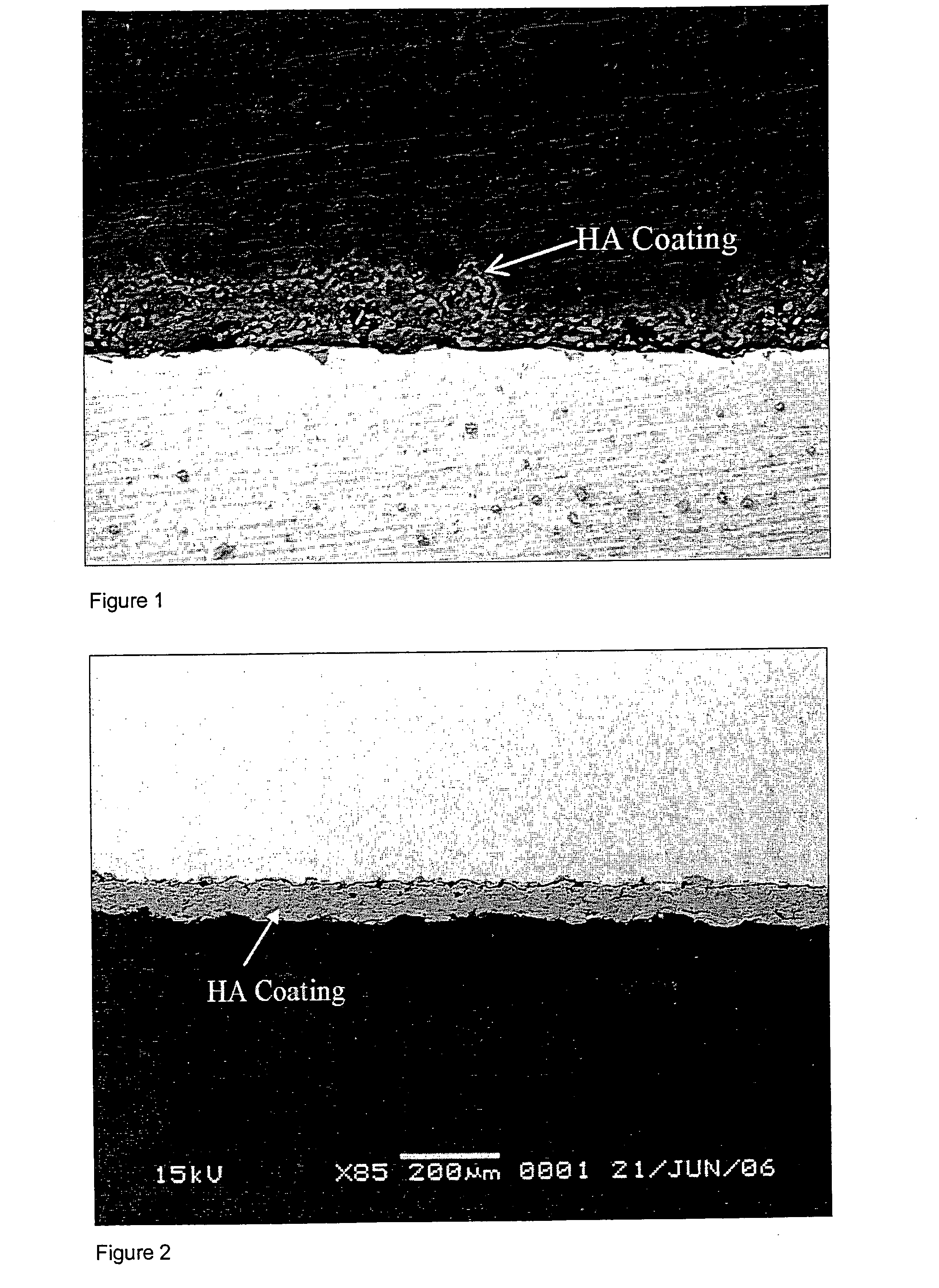
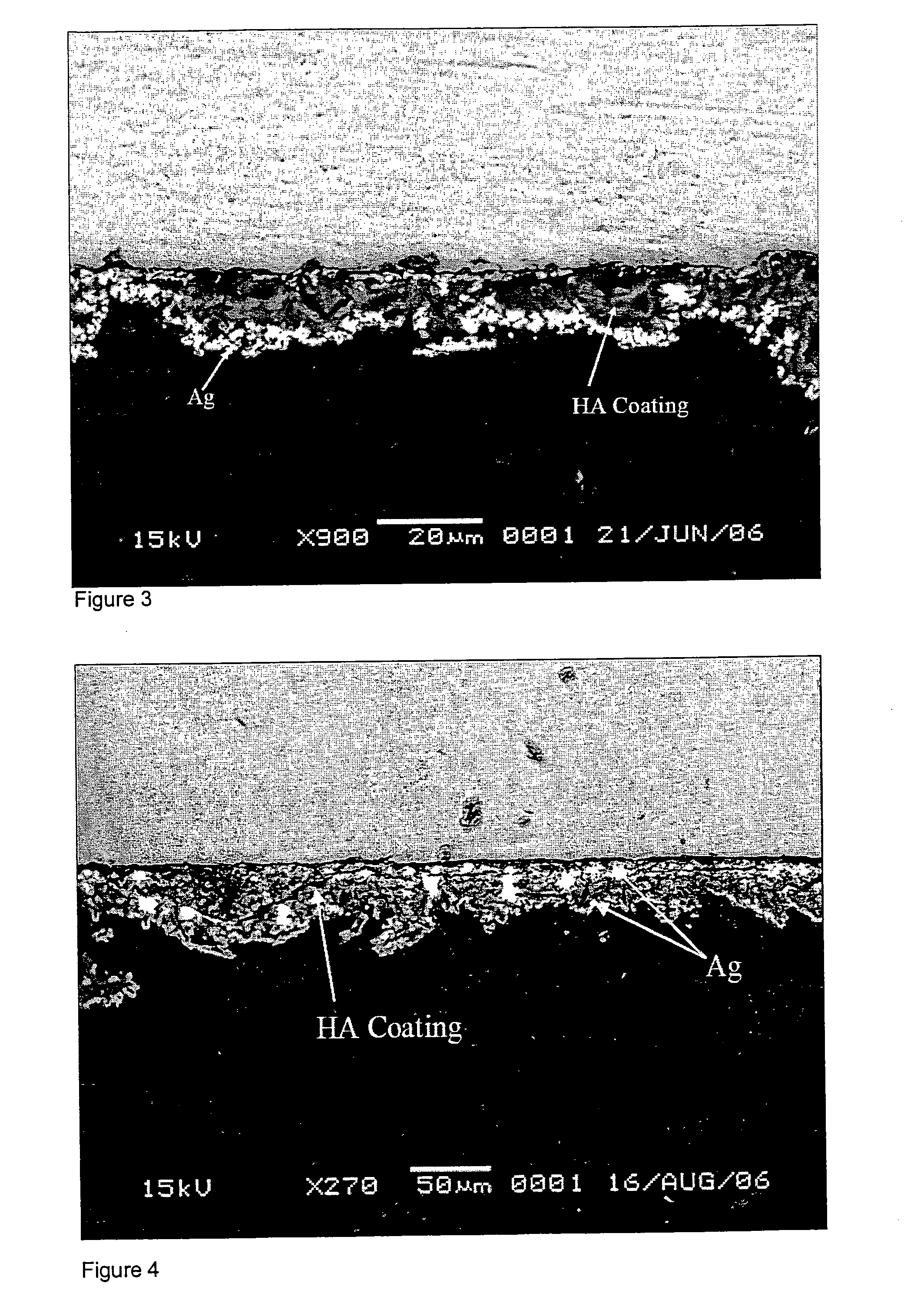
[0043]A disc was prepared in the same way as comparative example 1. This disc was then immersed in an AgNO3 solution at a concentration of 200 mg / 200 ml i.e. a 0.0058M solution for 24 hours at room temperature and in the dark. FIG. 3 shows an SEM micrograph of the resulting coating. As can be seen from the micrograph, a silver layer between the metal substrate and the hydroxyapatite coating can clearly be seen. The concentration of silver in the layer was measured as being 3.92 atomic percent.

example 2

[0044]A solution for electro-deposition of hydroxyapatite was prepared in accordance with comparative example 1. However, silver nitrate (AgNO3) was added to the solution in an amount of 100 mg / 200 mls of calcium phosphate solution prior to electrochemical deposition. Electrochemical deposition was then performed in the same way as in the comparative example 1 but in the dark. This produced a coating more rapidly and a thicker coating resulted. Silver was deposited within the crystal lattice of the HA. Using backscattered electron microscopy it was not possible to see any bright regions of silver deposition.

[0045]The resulting coating was measured as having a silver concentration of 0.38 atomic percent.

example 3

[0046]A layer of brushite was deposited as in comparative example 1. Silver was then applied by immersion in silver nitrate at 200 mg / 200 mls in the dark. This was dried and then another layer of brushite was deposited and converted to HA in the same way as in comparative example 1 except this was carried out in the dark. Another layer of silver was applied by immersing in solvernitrate solution 200 mg / 200 mls in the dark for 24 hours.

[0047]The resulting microstructure is illustrated in FIG. 4. As with FIG. 3, bright white silver layers can be seen in the micro graph and the silver was measured as being present at a level of 6.5 atomic percent in the coating of example 3.

Experimental Results

[0048]As can be seen from the electromicro graphs and the results of energy dispersive x-ray and x-ray diffraction analyses it is possible to tell the difference between an electrochemically deposited layer of hydroxyapatite and a plasma spray coated layer. It is also clear from the results that ...


PUM

PropertyMeasurementUnit
concentrationaaaaaaaaaa
electrically conductiveaaaaaaaaaa
porosityaaaaaaaaaa

Abstract

A method of surface treatment of at least part of a surface of an implant, said method comprising: electrochemical deposition of a layer containing calcium and phosphorus ions onto a metallic substrate; and incorporation of a therapeutic agent into said electrochemically deposited layer and an implant so treated.

Description

BACKGROUND[0001]The present invention relates to coatings on articles including prosthetic devices, in particular coatings on orthopaedic implants, with the incorporation into the coating of a therapeutic agent, particularly an antibacterial agent, preferably silver. The coating of articles with therapeutic agents has many uses including, but no limited to use on implants. Other uses may include surface treating items used in dentistry, for example. The invention is described below in relation to implants however.[0002]Implants and in particular bone implants are being used more and more. The use of bone replacement implants for bone fractures or the use of supports for weakened bones is now commonplace. Furthermore, implants for the replacement of bone which has been removed due to a tumour (e.g. a bone (marrow) tumour) or for joint replacement is also becoming increasingly common. The use of biomimetic coatings on such implants is widespread and this helps in the incorporation of ...

Claims


Application Information

Patent Timeline
Patent Type & Authority Applications(United States)
IPC IPC(8): A61F2/02B05D3/14
CPCA61C8/0013A61L27/32A61L27/54A61L2300/104A61L2300/252A61L2300/404C25D15/02A61L2300/606C25D5/10C25D5/34C25D5/48C25D9/04A61L2300/412
Inventor BLUNN, GORDONGHANI, YASERUNWIN, PAUL
Owner UCL BUSINESS PLC
Learn More