
Detecting gas compounds for downhole fluid analysis using microfluidics and reagent with optical signature

Inactive Publication Date: 2010-10-28
SCHLUMBERGER TECH CORP
View PDF26 Cites 35 Cited by
  • Summary
  • Abstract
  • Description
  • Claims
  • Application Information

AI Technical Summary

Benefits of technology

[0007]One of the advantages of the invention is that borehole fluid can be analyzed in situ. In particular, the reagent is introduced to the test sample fluid and the mixture is tested within the borehole. Consequently, time consuming fluid retrieval and errors caused by changes to fluid samples due to changes in conditions between the borehole and the environment are at least mitigated.
[0008]The use of microfluidic technology helps to achieve some of the advantages of the invention. Generally, microfluidics is a technique for processing and manipulating volumes of fluid on the order of nanoliters in a micrometer scaled channel known as a microchannel. As a result, fluid flow is laminar within the microchannel. A static or active mixer module may therefore used to enhance mixing of fluids and achieving a mixing ratio value of the mixed fluids. Microfluidics is distinct because manipulation of microliters of fluid in a laminar flow regime offers fundamentally new capabilities in the control of concentrations of molecules in space and time, the result of which facilitates detection of physical properties. It will therefore be appreciated that microfluidic technology offers advantages for analytical applications including small footprint, small sample and reagent volumes, the ability to carry out various processes such as separation and detection with high resolution and sensitivity, and low cost and reduced analysis time.

Problems solved by technology

Concentrations of CO2 and H2S are of interest because CO2 corrosion and H2S stress cracking caused by relatively high concentrations are leading causes of mechanical failure of production equipment.
However, retrieving samples for laboratory analysis is time consuming and prone to error.
For example, because hydrogen sulfide gas readily forms non-volatile and insoluble metal sulfides by reaction with many metals and metal oxides, analysis of a fluid sample retrieved with a metallic container can produce an inaccurate estimate of sulfide content.
This presents a technological problem because fluid analysis techniques that are known for use at the surface are generally impractical in the borehole environment due to size limitations, extreme temperature, extreme pressure, presence of water, and other factors.
Another technological problem is isolation of gases, and particular species of gas, from the borehole fluid, which commonly exist as multiphase fluids in borehole.
However, the system and the reagent described are not suitable for use in a downhole environment such as that encountered in oilfield operations.
However, a real-time microfluidic-based sensing system capable of operation over a wide temperature and pressure range and in harsh conditions such as those encountered in oilfield operations has not yet been developed.

Method used


Image

  • Detecting gas compounds for downhole fluid analysis using microfluidics and reagent with optical signature
  • Detecting gas compounds for downhole fluid analysis using microfluidics and reagent with optical signature
  • Detecting gas compounds for downhole fluid analysis using microfluidics and reagent with optical signature

Examples


Embodiment Construction

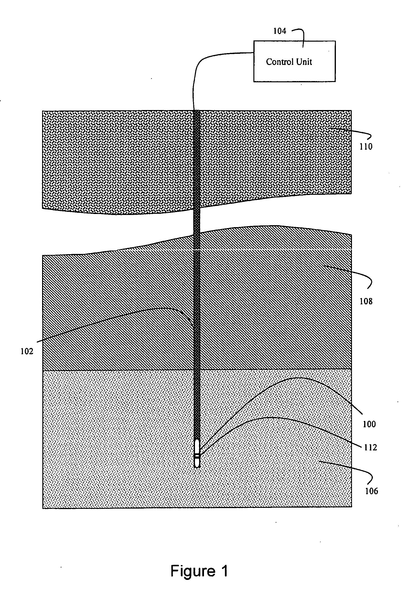
[0024]Referring to FIG. 1, a tool string 100 is utilized to measure characteristics of fluid in a borehole 102. The borehole may be formed through a hydrocarbon reservoir 106 adjacent to an impermeable layer 108, and various other layers which make up the overburden 110. The tool string, which may be part of a wireline logging tool string, logging-while-drilling tool string, or other device, is operable in response to a control unit 104 which may be disposed at the surface. The control unit 104 may also be capable of data analysis. The tool string 100 is connected to the control unit 104 by a logging cable for a wireline tool, or by a drill pipe string for a LWD tool. The tool string 100 includes a gas detection tool 112 which is lowered into the borehole to measure physical properties associated with fluid in the borehole or formation. Data gathered by the tool 112 may be communicated to the control unit in real time via the wireline cable or LWD telemetry.

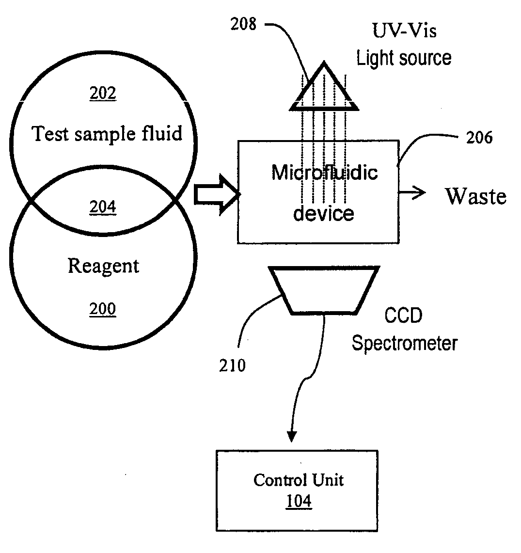
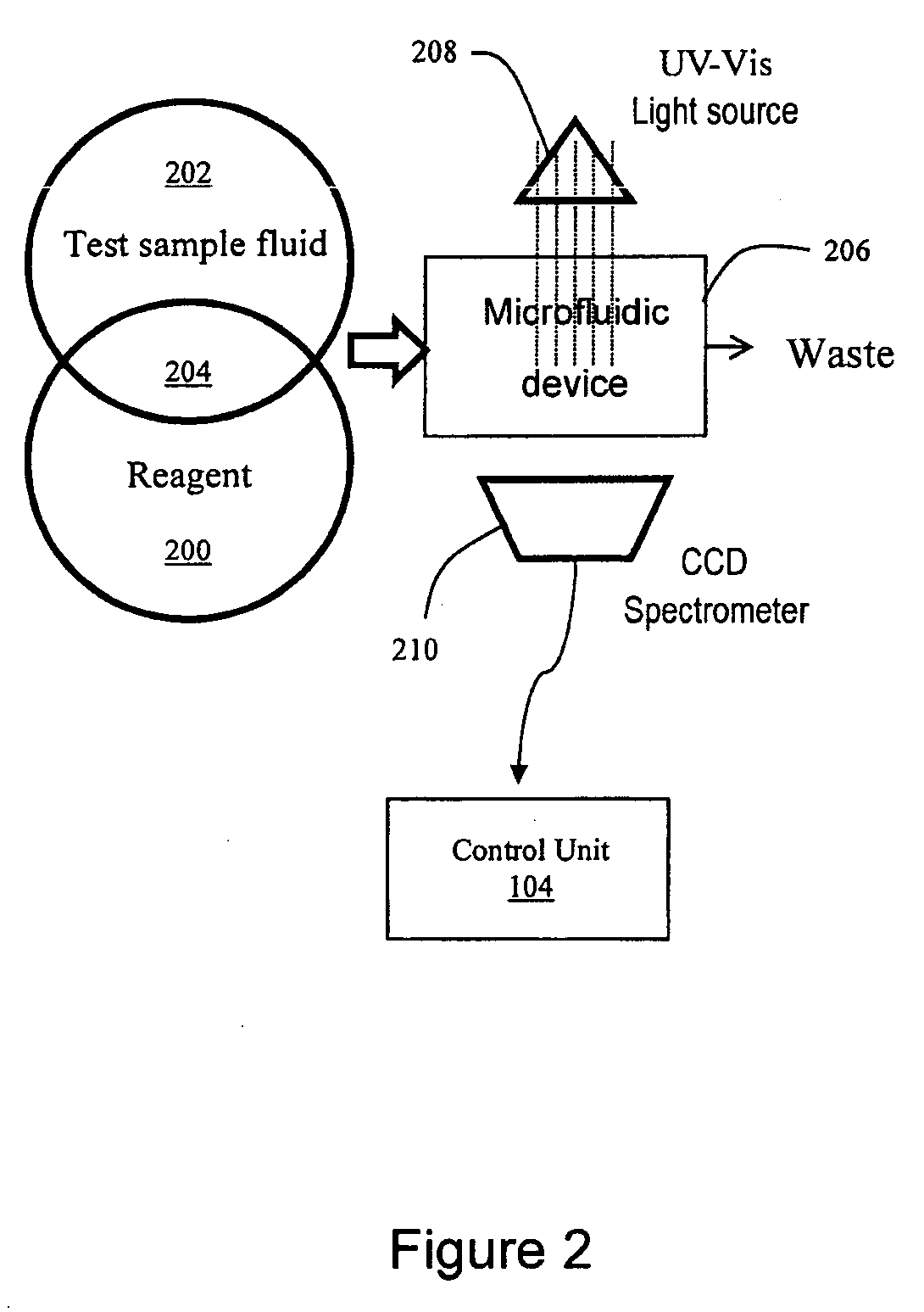
[0025]FIG. 2 illustrates ...


PUM


Abstract

A gas separation and detection tool for performing in situ analysis of borehole fluid is described. The tool operates by introducing a reagent to a test sample and causing the resulting mixture to flow through a microfluidic channel where optical testing is performed. The optical testing detects a change in a characteristic of the reagent in response to expose to one or more particular substances in the test sample. The test sample may be borehole fluid, a mixture of borehole fluid and scrubbing fluid subsequently mixed with reagent, a mixture of reagent and gas separated from borehole fluid, or a mixture of scrubbing fluid and gas separated from borehole fluid which is subsequently mixed with reagent. A membrane may be employed to separate one or more target gasses from the borehole fluid.

Description

FIELD OF THE INVENTION[0001]The invention is generally related to analysis of borehole fluid, and more particularly to in situ detection of gaseous compounds in a borehole fluid using a reagent which exhibits an optical signature in a microfluidic channel in response to exposure to certain substances.BACKGROUND OF THE INVENTION[0002]Phase behavior and chemical composition of borehole fluids are known to be useful information. For example, concentration of gaseous components such as carbon dioxide, hydrogen sulfide and methane in borehole fluid are indicators of the economic viability of a hydrocarbon reservoir. Concentrations of CO2 and H2S are of interest because CO2 corrosion and H2S stress cracking caused by relatively high concentrations are leading causes of mechanical failure of production equipment. CH4 concentration is of interest as an indicator of the calorific value of gas wells. It is therefore desirable to be able to perform fluid analysis quickly, accurately, reliably,...

Claims


Application Information

Patent Timeline
IPC IPC(8): E21B49/08
CPCG01N33/2823E21B47/102E21B47/113
Inventor LAWRENCE, JIMMYANGELESCU, DAN E.HARRISON, CHRISTOPHERYAMATE, TSUTOMUSULLIVAN, MATTHEW T.SCHROEDER, ROBERT J.VAN HAL, RONALD E.G.RAGHURAMAN, BHAVANI
Owner SCHLUMBERGER TECH CORP
Learn More