Self healing optical fiber cable assembly and method of making the same

a self-healing, optical fiber cable technology, applied in the field can solve the problems of optical fiber reliability, conventional fiber loss increase, and inability to contribute to the optical wave guide properties of optical fibers, so as to prolong the life of optical fiber cables, prevent complete failures, and increase reliability

Active Publication Date: 2010-11-04
THE BOEING CO
View PDF10 Cites 20 Cited by
  • Summary
  • Abstract
  • Description
  • Claims
  • Application Information

AI Technical Summary

Benefits of technology

[0010]This need for a self healing optical fiber cable assembly and method of making the same is satisfied and numerous advantages are discussed herein. Embodiments of the self healing optical fiber cable assembly and method of making the same may provide one or more of the following advantages: provides an optical fiber cable assembly and method that is self healing, extends the life of the optical fiber cable, increases reliability, prevents complete failures, helps fiber attenuation, and minimizes pistoning expansion and microbends thereby reducing transmission losses; provides an optical fiber cable assembly and method having a very small space hardened protection cable that contains a hot melt sealing material for the entire length of the cable that flows during natural thermal excursions (i.e., where an environment provides temperatures high enough to flow the sealing material), in order to seal microcracks, damages or defects in the buffer layer, cladding layer, and / or optical fiber core; provides an optical fiber cable assembly and method for which the self healing property eliminates, minimizes, or even prevents microcrack growth and defects in the optical fiber cable and decreases latent failures and failures in time, while providing increased mission robustness, in particular, such as associated with space environments and space applications; provides an optical fiber cable assembly and method that can be used for space worthy applications, such as space satellites, spacecraft and free space laser communication systems, as well as with sensors, terrestrial applications, aircraft, vehicles, underwater communication systems, long distance communication systems, extreme environments such as down hole fiber data logging, electrical and / or fiber routing in corrosive and / or explosive environments, pyroshock test chambers, and other suitable applications; provides an optical fiber cable assembly and method that can be used with glass, plastic, or electrical metal wire fibers; provides an optical fiber cable assembly and method that enhances the reliability of the optical fiber cable for space applications in a non-invasive way without requiring excessive accommodations from a host platform, i.e., does not require additional thermal controls or controls on fiber routing; provides an optical fiber cable assembly and method with a design that minimizes the design constraints of thermal environments for the fiber to ensure reliability; provides an optical fiber cable assembly and method that can minimize outgassing and can work with radiation resistance fibers / shielding while adding little, or possibly reducing, current cable size and weight; and provides an optical fiber cable assembly and method that manages pistoning expansion while providing flow protection using composite mechanical expansion joints and / or preconditioning processes during cable assembly.
[0011]In one of the embodiments of the disclosure, there is provided a self healing optical fiber cable assembly comprising: an elongated optical fiber core having a cladding layer adjacent to and surrounding the optical fiber core; a buffer layer adjacent to and surrounding the cladding layer; a sealing layer adjacent to and surrounding the buffer layer, wherein the sealing layer seals any microcracks or defects in the buffer layer, the cladding layer, and the optical fiber core; and, an outer protection layer adjacent to and surrounding the sealing layer, wherein an end of the outer protection layer is connected to a strain relief device to provide expansion protection to the cable assembly and to minimize strain on the cable assembly, and further wherein an end of the strain relief device is connected to an optical fiber module.
[0012]In another embodiment of the disclosure, there is provided a self healing optical fiber cable assembly comprising: an elongated optical fiber core having an integrated cladding and buffer layer surrounding the optical fiber core; a sealing layer adjacent to and surrounding the integrated cladding and buffer layer, wherein the sealing layer seals any microcracks or defects in the integrated cladding and buffer layer and in the optical fiber core; a constraining layer adjacent to and surrounding the sealing layer; and, an outer protection layer adjacent to and surrounding the constraining layer, wherein an end of the outer protection layer is connected to a strain relief device to provide expansion protection to the cable assembly and to minimize strain on the cable assembly, and further wherein an end of the strain relief device is connected to an optical fiber module. The outer protection layer may be corrugated.
[0013]In another embodiment of the disclosure, there is provided a self healing optical fiber cable assembly comprising: an elongated optical fiber core having an integrated cladding and buffer layer surrounding the optical fiber core; a sealing layer adjacent to and surrounding the integrated cladding and buffer layer, wherein the sealing layer seals any microcracks or defects in the integrated cladding and buffer layer and in the optical fiber core; and, an outer protection layer adjacent to and surrounding the sealing layer, wherein an end of the outer protection layer is connected to a strain relief device to provide expansion protection to the cable assembly and to minimize strain on the cable assembly, and further wherein an end of the strain relief device is connected to an optical fiber module. The outer protection layer may be corrugated.
[0015]In another embodiment of the disclosure, there is provided a self healing optical fiber cable assembly comprising: an elongated optical fiber core having a cladding layer adjacent to and surrounding the optical fiber core; a sealing layer adjacent to and surrounding the cladding layer, wherein the sealing layer seals any microcracks or defects in the cladding layer and the optical fiber core; and, an outer protection layer adjacent to and surrounding the sealing layer, wherein an end of the outer protection layer is connected to a strain relief device to provide expansion protection to the cable assembly and to minimize strain on the cable assembly, and further wherein an end of the strain relief device is connected to an optical fiber module.
[0016]In another embodiment of the disclosure, there is provided a method for making a self healing optical fiber cable assembly comprising the steps of: providing an elongated optical fiber core having a cladding layer and a buffer layer surrounding the optical fiber core; positioning a thermal plastic outer protection layer over the surrounded optical fiber core; inserting a hot melt sealing layer over an entire length of the surrounded optical fiber core, wherein the hot melt sealing layer seals any microcracks or defects in the surrounded optical fiber core; connecting an end of the outer protection layer to a strain relief device to provide expansion protection to the cable assembly and to minimize strain on the cable assembly; and, connecting an end of the strain relief device to an optical fiber module. The method may further comprise the step of positioning a constraining layer over the surrounded optical fiber core between the surrounded optical fiber core and the outer protection layer. The method may further comprise the step of positioning a strengthening layer between the constraining layer and the outer protection layer.

Problems solved by technology

These layers add strength to the fiber but do not contribute to its optical wave guide properties.
Optical fiber cables can be very flexible but conventional fiber loss increases if the optical fiber cable is bent, such as the cable being bent around corners or wound around a spool.
In addition, optical fiber reliability is dependant on the buffer layer and / or cladding layer damage, such as microcracks, that can grow with time when the optical fiber is exposed.
Such microcracks can result in latent failures, failures in time, decreased robustness, decreased reliability, and shortened lifespan of the optical fiber and associated optical fiber cable and devices.
Moreover, defects or damage to the buffer layer and / or cladding layer can occur as part of the manufacturing process, handling, and post-processing, and with time, can lead to cracks in the optical fibers.
In addition, damage to the buffer layer and / or cladding layer can propagate into the optical fiber glass core.
Buffer layer and / or cladding layer defects may be caused by fiber handling, mechanical motion, or rubbing, such as during the life of a space mission.
Such defects may be difficult to screen out and may be a source for latent failures.
However, such devices and methods can require additional thermal controls and / or controls on fiber routing which may result in increased complexity and costs and which may constrain the thermal environment for the optical fiber, thus resulting in decreased reliability.
In addition, the cable protection materials often surround only the splice or a partial portion of the optical fiber cable and do not surround the entire length of the optical fiber cable, thus limiting the protection to the optical fiber cable.
Thereafter, the defects due to handling and / or mission environment may be difficult to remove or repair.
Although damage or defects may be pre-screened to promote reliability, once a defect commences, time will result in failure of the optical fiber cable.
Known optical fiber cables are not self healing to protect against such damage.
However, such known mechanical clamps or coupling devices may subject the optical fiber cable to excessive clamping or coupling pressure or damage, thus resulting in reduced light transmission.
Moreover, insufficient thermal conditioning and / or clamping or coupling may permit undesirable movement of the optical fibers within the cable.
Pistoning expansion can create strain on the optical fibers and induce transmission losses.
At the least, fiber bending around the splices may occur, and at the worst the optical fibers may be broken which results in devastation of the system.
Such problems are particularly likely to occur in environments where significant temperature variations cause expansion and contraction, which result in clamping pressure variations.
In addition, optical fibers may also be susceptible to outgassing and decreased radiation resistance, such as may occur in aerospace applications.
However, this can result in exposed adhesive within the intended package.
Since many adhesives, such as epoxy, outgas or emit undesirable materials, such as water or solvents, this may result in contamination of the interior of the package with the resulting outgassed materials.
However, such known methods and devices can be costly and can increase the size and weight of the optical fiber cable.

Method used


Image

  • Self healing optical fiber cable assembly and method of making the same
  • Self healing optical fiber cable assembly and method of making the same
  • Self healing optical fiber cable assembly and method of making the same

Examples


Embodiment Construction

[0033]Disclosed embodiments will now be described more fully hereinafter with reference to the accompanying drawings, in which some, but not all disclosed embodiments are shown. Indeed, several different embodiments may be provided and should not be construed as limited to the embodiments set forth herein. Rather, these embodiments are provided so that this disclosure will be thorough and complete and will fully convey the scope of the disclosure to those skilled in the art.

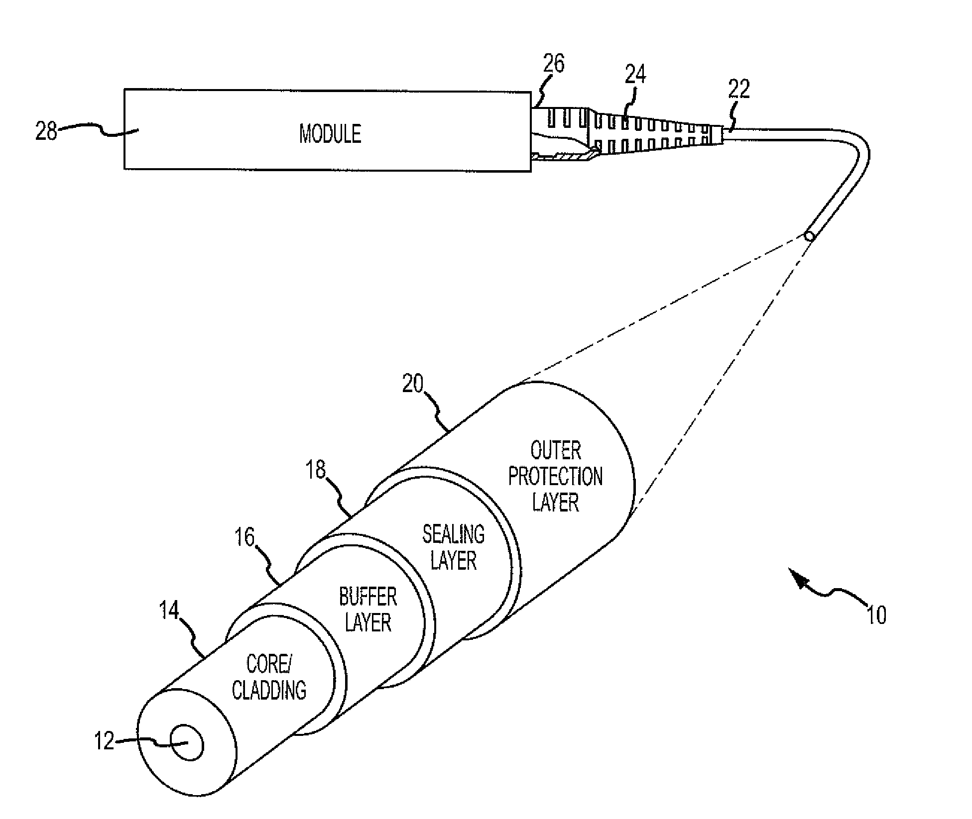
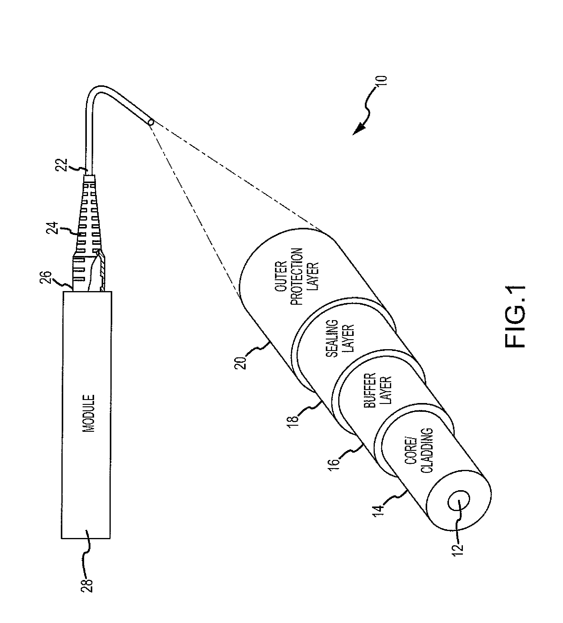
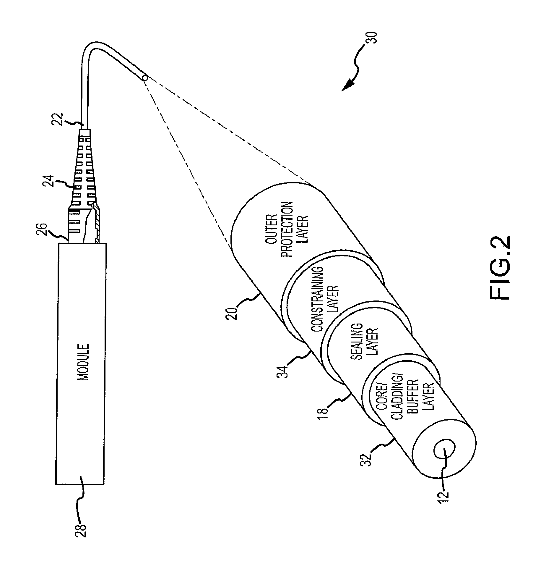
[0034]The disclosure provides for a self healing optical fiber cable assembly and method of making the same. The self healing optical fiber cable assembly and method of the disclosed embodiments may be used in connection with various applications including, but not limited to, space worthy applications, such as space satellites, spacecraft and free space laser communication systems, as well as with sensors, terrestrial applications, aircraft, vehicles, underwater communication systems, long distance communication...


PUM

PropertyMeasurementUnit
outer diameteraaaaaaaaaa
inner diameteraaaaaaaaaa

Abstract

In one of the embodiments there is disclosed a self healing optical fiber cable assembly comprising an elongated optical fiber core having a cladding layer, a buffer layer, a sealing layer that seals any microcracks or defects in the buffer layer, the cladding layer, and the optical fiber core, and, an outer protection layer, wherein an end of the outer layer is connected to a strain relief device to provide expansion protection to the cable assembly and to minimize strain on the cable assembly, and further wherein an end of the strain relief device is connected to an optical fiber module. The cable assembly may further comprise a constraining layer and / or a strengthening layer. There is also disclosed a method of making a self healing optical fiber cable assembly.

Description

BACKGROUND[0001]1) Field of the Disclosure[0002]The disclosure relates to optical fiber cables, and more particularly, to a self healing optical fiber cable assembly and method of making the same.[0003]2) Description of Related Art[0004]An optical fiber cable typically comprises a glass or plastic optical fiber that carries light along its length and various layers of protective and strengthening materials surrounding the optical fiber. Optical fiber cables are widely used in fiber optic communications which permit transmission over longer distances and at higher data rates than other forms of communications. Optical fiber cables may be used in space satellites and space environments, aircraft, sensors, light guides where bright light needs to be shone on a target without a clear line-of-sight path, imaging optics, and other suitable applications. An optical fiber is a cylindrical dielectric waveguide that transmits light along its axis by the process of total internal reflection. T...

Claims


Application Information

Patent Timeline
Patent Type & Authority Applications(United States)
IPC IPC(8): G02B6/44B23P25/00
CPCG02B6/443Y10T29/49885G02B6/3887G02B6/3888
Inventor NODDINGS, KENNETH C.
Owner THE BOEING CO
Why Eureka
Try Eureka