Sample collection apparatus

a collection apparatus and sample technology, applied in the field of sample collection apparatus, can solve the problems of affecting the signal level detected at the waveguide, further complicating the biosensor and the signal level observed, and reducing the risk of spreading disease, reducing the cost and size of the apparatus, and being highly compact.

Active Publication Date: 2010-11-04
RAPID BIOSENSOR SYST LTD
View PDF11 Cites 14 Cited by
  • Summary
  • Abstract
  • Description
  • Claims
  • Application Information

AI Technical Summary

Benefits of technology

[0035]In a subsidiary aspect, said marking means includes lysing means for causing lysis of the components present in the sample, thereby enhancing measurement sensitivity of the system by increasing the number of available potential optical labelling sites.
[0222]The optical interfacing means preferably comprises a prism for guiding interrogating radiation from the interrogating means to the sample, and for guiding response radiation from the sample back to the interrogating means. Use of a single optical component for bi-directional optical radiation propagation enables the cost and size of the apparatus to be potentially reduced. More preferably, the prism is a dove-type prism; such a prism is susceptible to being used, for example, in evanescent-wave optical interrogation of samples, especially samples subjected to fluorophore tagging.

Problems solved by technology

These wash-steps complicate the system and make it necessary for a relatively skilled operator to carry out the testing.
A disadvantage of this sensor is that bulk scattering by an optical waveguide forming a part of the sensor can affect the signal level detected at the waveguide.
Moreover, multilayer construction configurations of the optical waveguide serve to further complicate the biosensor and the complexity of signal levels observed.
The coupling of the resonant wavelength is facilitated by an optical grating located at either the interface between the dielectric body and the medium or between the dielectric body and the sensitized coating, which can potentially result in alignment problems.
Furthermore, the light is reflected many times within the waveguide and as such the intensity observed is subject to losses due to scattering.
The device is of a complex design which employs a beam splitter and lens system susceptible to scattering losses.
This device is of relatively high cost and complexity.
The apparatus relies upon personnel performing tests to transfer samples onto a disposable element of the apparatus and as such is not a ‘safe’ method of handling pathogenic samples.
Such an analysis results in a complex problem of co-addition to determine all of the molecular species present.
The use of a mass spectrometer is expensive and requires the incorporation of vacuum equipment; thus this test is of high cost and is not portable.
Such an assay would not be appropriate for the collection of pathogens contained within sputum / mucus from the upper lung area.
Such an approach means that the sample is transferred to another system which immediately gives rise to safety issues concerning safe sample handling and speed of testing the samples.
In the detection of viruses and bacteria, such as mycobacterium tuberculosis, the device is inappropriate as there is no simple way provided to isotopically label the pathogen nor is there any simple way of forming a simple breakdown product.
The apparatus entirely encloses the patient and, as such, is not portable.
The device is not easily portable.
Contemporary bacterial tests are mainly based on complex laboratory assays and are therefore potentially expensive and are not especially suitable for field use.
These rapid tests are primarily based on the analysis of sputum / mucus samples from upper lung regions; however, the collection and handling of such samples is hazardous to personnel conducting and / or supervising such testing.
Thus, both timescale and potential pathogen transmission problems make these contemporary tests difficult to execute in field locations.
Furthermore, at the current state of the art for the field-testing of tuberculosis (TB), a ‘standard’ skin test employed is compromised by HIV status and so the only method currently used in the third world is that of smear microscopy on sputum / mucus samples.
None of the known systems reviewed above adequately addresses these problems.

Method used


Image

  • Sample collection apparatus
  • Sample collection apparatus
  • Sample collection apparatus

Examples


Embodiment Construction

[0258]In the following description, embodiments of a biological measurement system will initially be described in overview. Later, component parts of the embodiments and their associated biochemistry will be described in more detail.

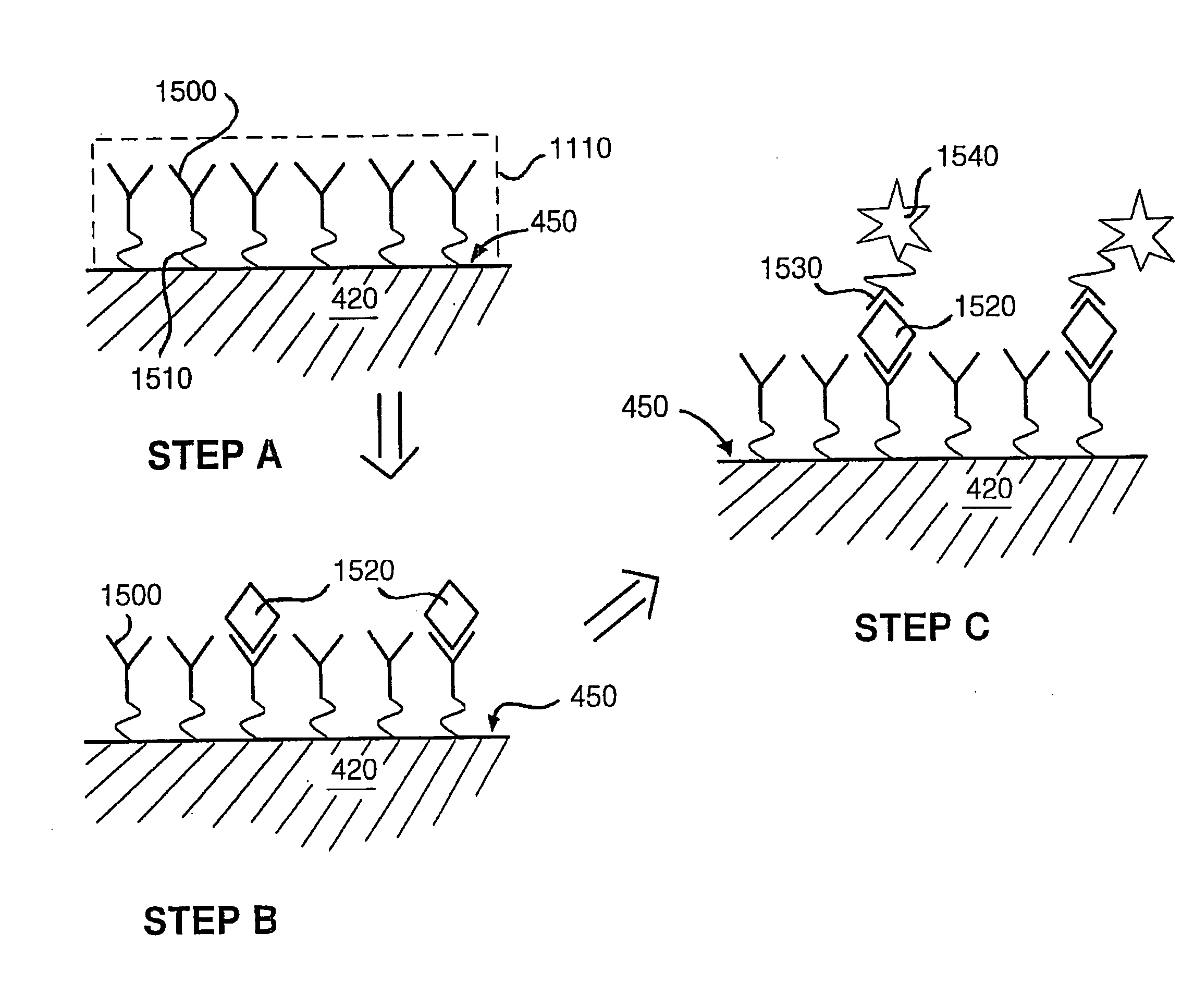
[0259]The system described herein employs evanescent wave spectroscopy and evanescent wave fluorimetry to detect the presence of a pathogenic substance using an immunoassay technique.

1. System Overview

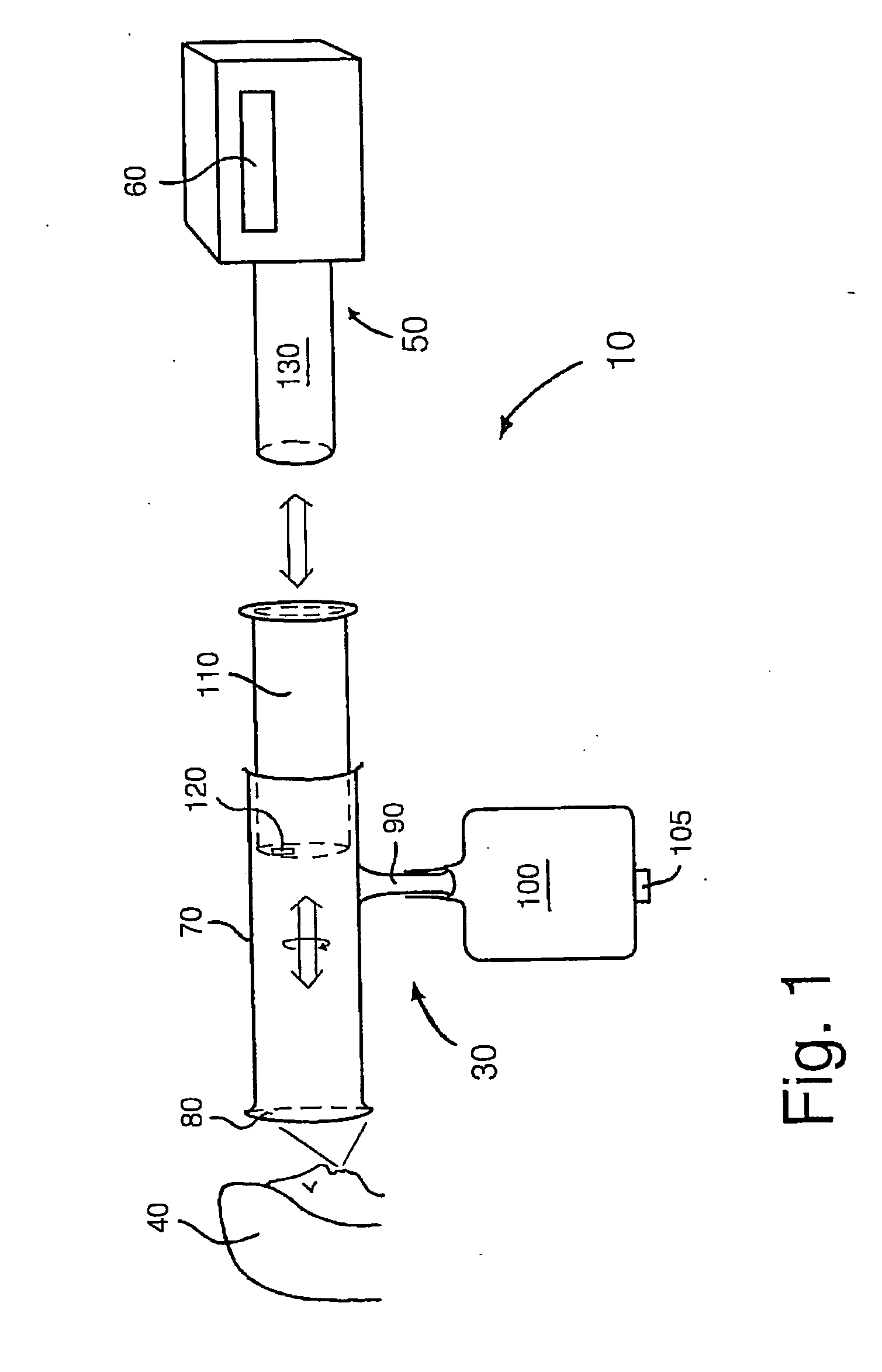
[0260]Referring firstly to FIG. 1, there is shown a biological measurement system according to the invention. The system is indicated generally by 10 and comprises a sample collection unit indicated by 30, and a corresponding complementary reader unit indicated by 50. For displaying test results, the reader unit 50 includes a readout display 60. The collection unit 30 is adapted for collecting exhaled material from a user 40, such material providing test samples for subsequent analysis.

[0261]The collection unit 30 is designed to engage mechanically into the...


PUM

PropertyMeasurementUnit
diametersaaaaaaaaaa
diametersaaaaaaaaaa
droplet sizesaaaaaaaaaa

Abstract

A sample collection apparatus which measures biological samples and can be used to provide the early detection of respiratory diseases, for example tuberculosis induced by the pathogen mycobacterium tuberculosis. The sample collection apparatus has a sample collection unit and a corresponding complementary reader unit. The collection unit collects a sample exhaled from the user through a collection vessel with an optical interrogation region. The sample is spread on the inside of the vessel over the interrogation region and subsequently analyzed. The test results are displayed via the reader unit.

Description

FIELD OF THE INVENTION[0001]The present invention relates to a sample collection apparatus; more particularly, but not exclusively, the invention relates to an apparatus for providing early detection of respiratory disease, for example tuberculosis induced by the pathogen mycobacterium tuberculosis. REVIEW OF THE ART[0002]Numerous biological measurement systems are known in the art for detecting various forms of pathogens, for example bacteria, viruses, moulds and fungi.[0003]In an article entitled ‘Detection of Antibody-Antigen Reactions at a glass-liquid interface as a Novel Optical Immunoassay Concept’, Proceedings of 2nd Optical Fibre Conference (Stuttgart 1984) pp. 75, R. M. Sutherland et al. describe an optic waveguide apparatus wherein an antibody species is covalently immobilized onto a surface of a planar or fibre-optic waveguide. A sample solution comprising an antigen is presented to the surface, whereat the antigen is immobilized by the antibody species. The antigen is i...

Claims


Application Information

Patent Timeline
Patent Type & Authority Applications(United States)
IPC IPC(8): G01N33/53C12M1/26C12M1/33C12Q1/70G01N1/22G01N1/24G01N1/28G01N21/64G01N21/77G01N33/543G01N33/545G01N33/569G01N33/58
CPCA61B5/097A61B5/411G01N21/6428G01N21/648G01N21/7703G01N2333/35G01N33/56911G01N33/5695G01N33/582G01N2001/2244G01N2001/247G01N33/54373G01N33/533Y02A50/30
Inventor MCCASH, ELAINE MARIEMURRAY, NICOL JOHN
Owner RAPID BIOSENSOR SYST LTD
Why Eureka
Try Eureka