Eureka AIR delivers breakthrough ideas for toughest innovation challenges, trusted by R&D personnel around the world.

Selective UV-Ozone Dry Etching of Anti-Stiction Coatings for MEMS Device Fabrication

Active Publication Date: 2010-12-16
ANALOG DEVICES INC
View PDF7 Cites 13 Cited by
  • Summary
  • Abstract
  • Description
  • Claims
  • Application Information

AI Technical Summary

Benefits of technology

[0002]The invention generally relates to MEMS devices and, more particularly, the invention relates to sel

Problems solved by technology

Undesirably, extremely clean microstructure surfaces often stick together if they come into contact.
When the surfaces remain stuck together, the device often is inoperable.
Although the seal glass bonding has been incorporated in many MEMS products, including accelerometers, it imposes several constraints including larger die size on the order of 100 micron, contamination of die enclosure during screen printing, and contamination from lead used to reduce the melting temperature of glass.
However, the existence of the anti-stiction coating on the bond lines can negatively impact adhesion and can reduce the bond shear strength, which can result in an incomplete or insufficient wafer-to-wafer bond.
These things can lower yield (i.e., the number of acceptable devices realized per wafer) and also can lead to device failures.
Plasma etching has been used to remove anti-stiction coating material from bond line surfaces, but plasma etching is generally non-selective and can result in removal of anti-stiction coating materials from movable MEMS structures that require stiction prevention.

Method used


Image

  • Selective UV-Ozone Dry Etching of Anti-Stiction Coatings for MEMS Device Fabrication
  • Selective UV-Ozone Dry Etching of Anti-Stiction Coatings for MEMS Device Fabrication
  • Selective UV-Ozone Dry Etching of Anti-Stiction Coatings for MEMS Device Fabrication

Examples


Embodiment Construction

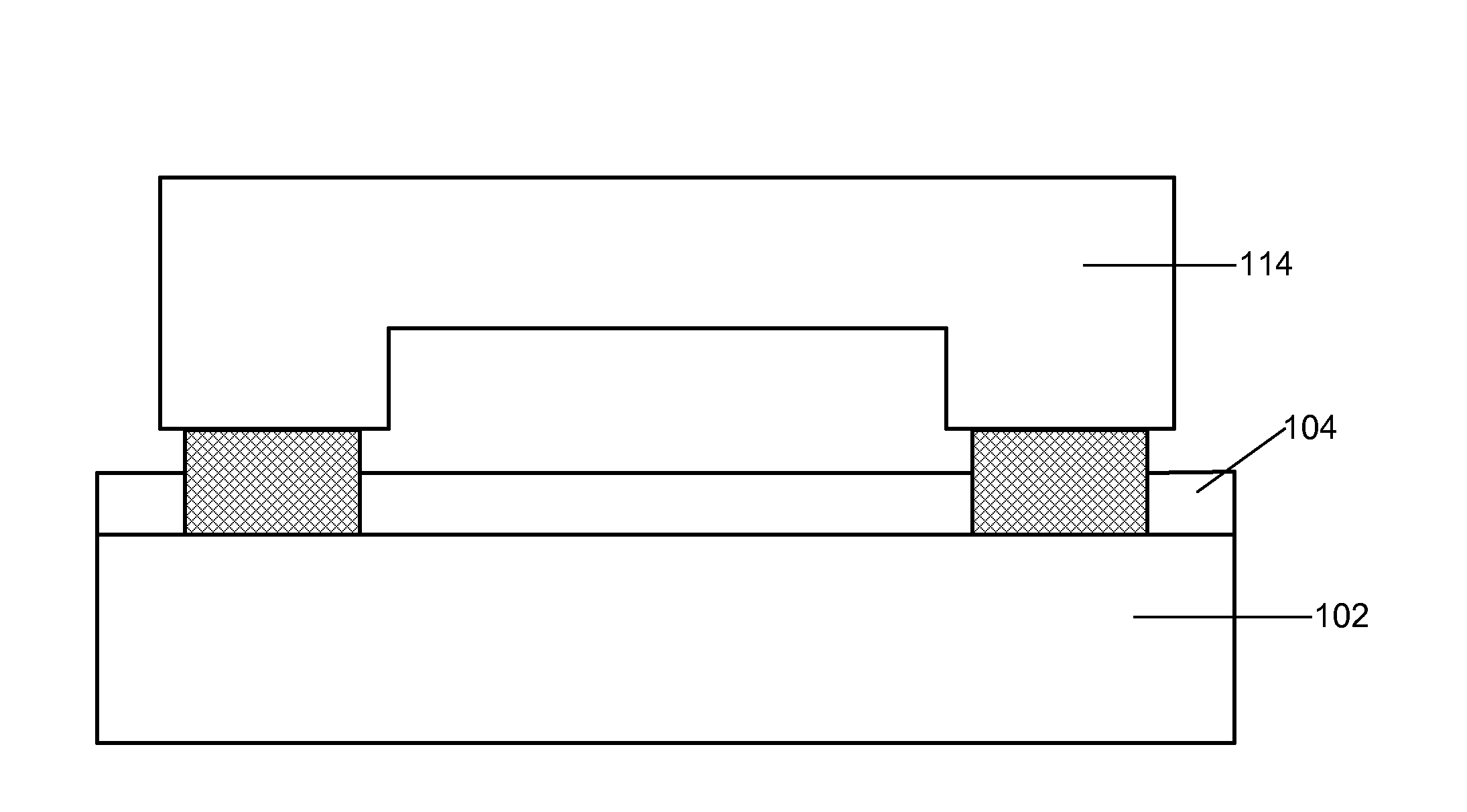
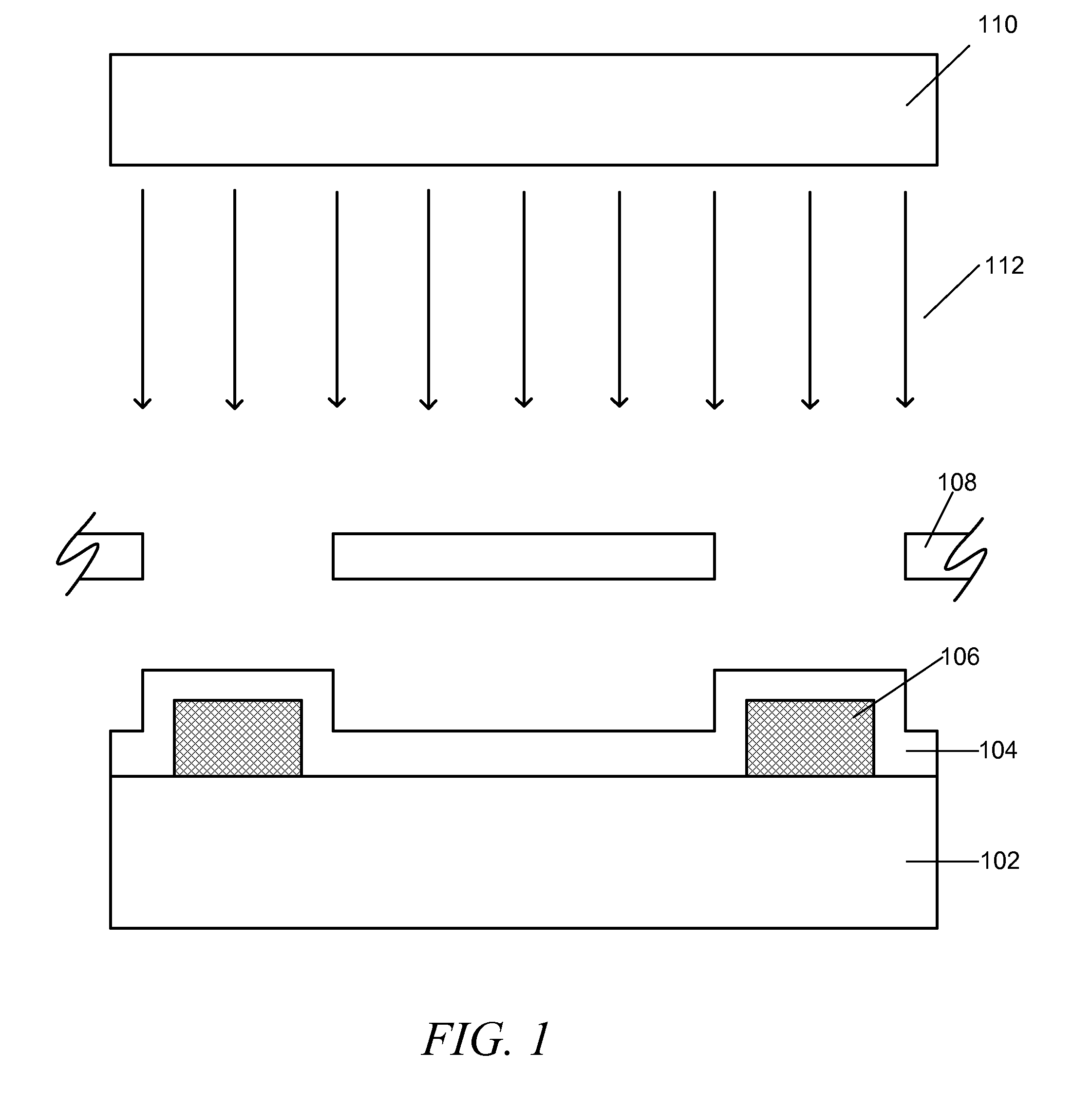
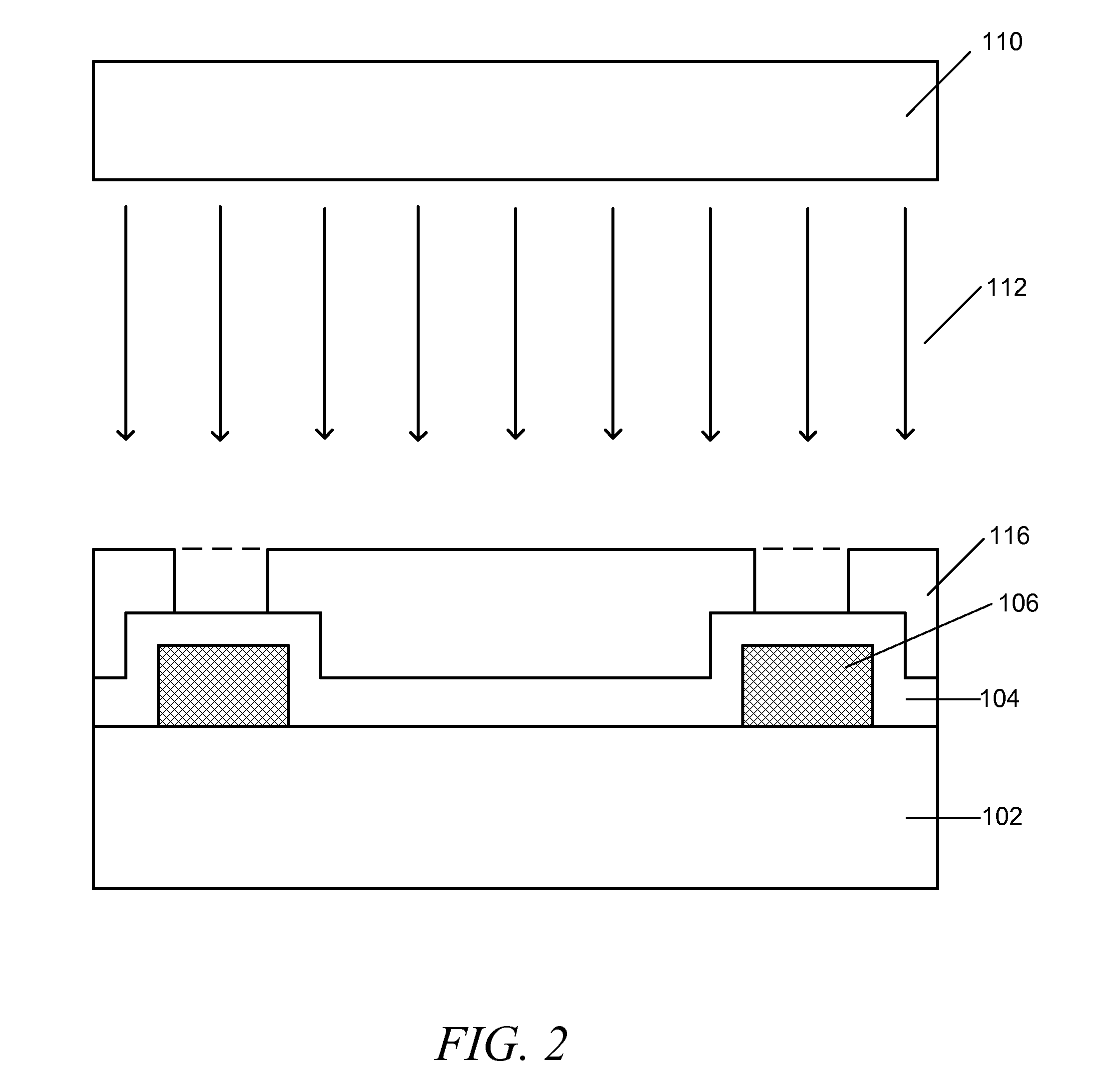
[0026]In exemplary embodiments of the present invention, organic anti-stiction coatings such as, for example, hydrocarbon and fluorocarbon based self-assembled organosilanes and siloxanes applied either in solvent or via chemical vapor deposition, are selectively etched using a UV-Ozone (UVO) dry etching technique in which the portions of the organic anti-stiction coating to be etched are exposed simultaneously to multiple wavelengths of ultraviolet light that excite and dissociate organic molecules from the anti-stiction coating and generate atomic oxygen from molecular oxygen and ozone so that the organic molecules react with atomic oxygen to form volatile products that are dissipated, resulting in removal of the exposed portions of the anti-stiction coating. A shadow mask (e.g., of glass or quartz), a protective material layer, or other mechanism may be used to selective expose the portions of the anti-stiction coating to be UVO etched. Such selective UVO etching may be used, for...


PUM

PropertyMeasurementUnit
Wavelengthaaaaaaaaaa
Temperatureaaaaaaaaaa

Abstract

Organic anti-stiction coatings such as, for example, hydrocarbon and fluorocarbon based self-assembled organosilanes and siloxanes applied either in solvent or via chemical vapor deposition, are selectively etched using a UV-Ozone (UVO) dry etching technique in which the portions of the organic anti-stiction coating to be etched are exposed simultaneously to multiple wavelengths of ultraviolet light that excite and dissociate organic molecules from the anti-stiction coating and generate atomic oxygen from molecular oxygen and ozone so that the organic molecules react with atomic oxygen to form volatile products that are dissipated, resulting in removal of the exposed portions of the anti-stiction coating. A hybrid etching process using heat followed by UVO exposure may be used. A shadow mask (e.g., of glass or quartz), a protective material layer, or other mechanism may be used to selective expose the portions of the anti-stiction coating to be UVO etched. Such selective UVO etching may be used, for example, to expose wafer bond lines prior to wafer-to-wafer bonding in order to increase bond shear and adhesion strength, to expose bond pads in preparation for electrical or other connections, or for general removal of anti-stiction coating materials from metal or other material surfaces. One specific embodiment uses two wavelengths of ultraviolet light, one at around 184.9 nm and the other at around 253.7 nm.

Description

CROSS-REFERENCE TO RELATED APPLICATION(S)[0001]This patent application claims the benefit of U.S. Provisional Patent Application No. 61 / 186,958 filed Jun. 15, 2009, which is hereby incorporated herein by reference in its entirety.FIELD OF THE INVENTION[0002]The invention generally relates to MEMS devices and, more particularly, the invention relates to selective etching of anti-stiction coatings in MEMS device fabrication using a UV-Ozone dry etching technique.BACKGROUND OF THE INVENTION[0003]Semiconductor technologies often form extremely clean microstructure surfaces on microelectromechanical devices (often referred to as “MEMS devices”). Undesirably, extremely clean microstructure surfaces often stick together if they come into contact.[0004]When the surfaces remain stuck together, the device often is inoperable. This concept of surface sticking is known in the art as “stiction.”[0005]A number of different factors can contribute to stiction. For example, among other things, stict...

Claims


Application Information

Patent Timeline
IPC IPC(8): H01L21/302H01L23/28
CPCB81C1/00269B81C2201/0181B81C2201/112B81C2203/0118
Inventor HANCER, MEHMET
Owner ANALOG DEVICES INC
Why Eureka
Eureka Blog
Learn More