Monolithic folded f-p cavity and semiconductor laser using the same

a monolithic, f-p cavity technology, applied in semiconductor lasers, instruments, optical elements, etc., can solve the problems of poor system reliability, large volume of f-p cavity, and sensitive outside inference of existing folded f-p cavities composed of discrete components, and achieve the effect of convenient fabrication

Active Publication Date: 2011-02-10
NAT INST OF METROLOGY CHINA
View PDF4 Cites 7 Cited by
  • Summary
  • Abstract
  • Description
  • Claims
  • Application Information

AI Technical Summary

Benefits of technology

[0009]To solve the above-mentioned problems in existing folded F-P cavity composed of discrete components, such as unsatisfactory reliability, sensitive to outside inferences, bulky and complicated construction, a novel monolithic folded F-P cavity is provided, which is suitable for semiconductor laser and can be easily fabricated. Rather than composed of separate components, the F-P cavity according to the present invention is formed by a monolithic optical element, which is made of material having low transmission loss with respect to a certain spectrum range. Said monolithic optical element is formed in such a way that the light beam entering through an input / output coupling surface of the monolithic optical element is reflected several times between the input / output coupling surface and at least two high reflection surfaces within the monolithic optical element, and then at least a part of the light radiates out of the input / output coupling surface along a path collinear with the incident light but in an opposite direction thereto. Thus the similar function as a conventional F-P cavity composed of discrete components can be realized.

Problems solved by technology

Usually, the external-cavity semiconductor lasers mentioned above have output spectrum linewidth of up to several hundreds KHz or even up to several MHz, and DFB semiconductor lasers provide even wider linewidth, which is undesirable for many application situations.
However, due to the difficulty of accurate turning of discrete components, existing folded F-P cavities composed of discrete components are sensitive to outside inferences caused by sound, mechanical vibration and temperature influence.
Further, such F-P cavity usually has a relative large volume and poor system reliability.

Method used


Image

  • Monolithic folded f-p cavity and semiconductor laser using the same
  • Monolithic folded f-p cavity and semiconductor laser using the same
  • Monolithic folded f-p cavity and semiconductor laser using the same

Examples


first embodiment

[0035]FIG. 4 shows the structure of monolithic folded F-P cavity 5 according to this invention. According to this preferred embodiment, the monolithic optical element forming the F-P cavity is a prism with cross-section of right trapezoidal shape, which is made of monolithic material having low transmission loss for the resulted laser radiation spectrum range, such as low transmission loss quartz glass, or other optical glass (FIG. 4 shows the cross-section of the cavity, all lateral edges of the prism are vertical to that cross-section). As an example, the prism is formed in such a way that its trapezoidal cross-section has a bottom length of 15 mm and a height of 13 mm, and the length of lateral edges of the prism is 6 mm (the thickness of the monolith). Those skilled in the art will understand that the dimensions mentioned above are only illustrative, and other shapes and / or sizes are also possible for the monolithic element of the folded F-P cavity.

[0036]The side where the right...

second embodiment

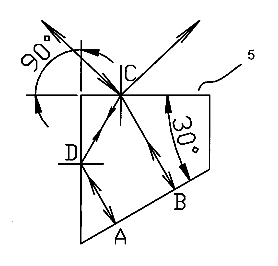
[0039]FIG. 5 schematically shows the structure of the monolithic folded F-P cavity according to this invention. In FIG. 5, point C represents the position where a light is incident on a coupling surface, and points A and B represent the corresponding reflection positions of the two high reflection surfaces of monolithic optical element 5, wherein only one path folding occurs on the coupling surface within monolithic optical element 5.

[0040]In this case, a light beam enters monolithic optical element 5 at point C on the coupling surface, then, after refraction, is perpendicularly incident to point B on the first high reflection surface coated with high reflectivity coating, where it is reflected back to point C along the original path, and, after second reflection, folded towards the second high reflection surface coated with high reflectivity coating, and then perpendicularly incident to point A thereon, from which it returns back to point C along the original path, where both trans...


PUM


Abstract

This invention relates to a monolithic folded F-P cavity used for semiconductor laser, which is composed of a monolithic optical element. The monolithic optical element is made of the material having low propagation loss for a certain spectrum range. Light entering through an input/output coupling surface of the monolithic optical element is reflected several times between the input/output coupling surface and at least two high reflection surfaces within the monolithic optical element, and then at least one part of the light exits through the input/output coupling surface along the path which is collinear with the incident light but in an opposite direction. By means of integrating reflecting and coupling parts of the folded F-P cavity within a single monolithic optical material, this invention greatly improves the reliability of the F-P cavity, and has other advantages, such as insensitive to outside interferences, smaller size, simpler structure and easy usage. A semiconductor laser using the monolithic folded F-P cavity is also provided.

Description

TECHNICAL FIELD[0001]This invention generally relates to semiconductor laser techniques, and, specifically, to a Fabry-Perot (F-P) resonant cavity composed of a monolithic optical element, as well as a semiconductor laser using such a F-P resonant cavity.BACKGROUND[0002]Semiconductor lasers, including distributed feedback (DFB) semiconductor lasers and external-cavity semiconductor lasers, are important laser source used in scientific research and industry.[0003]Conventional external-cavity semiconductor lasers are usually implemented in Littrow configuration and in Littman or grazing incidence configuration, which are shown in FIGS. 1 and 2, respectively. FIG. 1 is a schematic diagram showing the structure of an external-cavity semiconductor laser with Littrow configuration, wherein laser beams emitted from semiconductor laser diode 1 are converged into parallel beams after passing through aspheric collimator 3, and then imping onto grating 12 at an incidence angle θi. After first ...

Claims


Application Information

Patent Timeline
Patent Type & Authority Applications(United States)
IPC IPC(8): H01S3/105H01S5/14H01S3/081G02B5/04
CPCG02B5/04G02B5/18G02B5/1814G02B5/1861H01S5/143H01S3/08059H01S5/02248H01S5/141G02B5/284H01S5/02325
Inventor ZANG, ERJUNCAO, JIANPINGLI, YEFANG, ZHANJUN
Owner NAT INST OF METROLOGY CHINA
Why Eureka
Try Eureka