Phototherapy mask

Inactive Publication Date: 2011-02-17
FRANCIS STACY
View PDF10 Cites 53 Cited by
  • Summary
  • Abstract
  • Description
  • Claims
  • Application Information

AI Technical Summary

Benefits of technology

[0016]As illustrated in FIGS. 3a and 3b, “multi-mode fiber” supports more than one mode of light propagation through the core. In multi-mode fiber, light propagates down the core along multiple paths, some close to the longitudinal axis and others at various angles greater than the critical angle θc. Since light rays at different angles will have different path lengths, they will take different times to traverse the fiber. This causes the light energy in a multi-mode fiber to spread out and diffuse, tending to distribute the light energy uniformly along the length of the fiber. Such diffusion in multi-mode fibers can be reduced by using a “graded index” core/cladding boundary, in which the decrease of refractive index is gradual, as shown in FIG. 3b. On the other hand, diffusion can be maximized by using a “step index” boundary, in which the decrease of refractive index is abrupt, as shown in FIG. 3a.
[0017]Consequently, to achieve optimal uniformity of light energy dosage in an LED-driven optical fiber phototherapy mask, a step-index multi-mode fiber must be used. This choice also is consistent with LED-coupling imperatives discussed above, since step-index multi-mode fibers have large core diameters and high numerical apertures, so that they are very efficient at collecting light. Step-index multi-mode fiber is also capable of transmitting more power than other fiber types, thus allowing fewer fibers to be used to meet the phototherapy dosage requirements.
[0018]Dosage uniformity along the fiber depends not only on uniform distribution of light energy within the fiber, but also on uniform light emission from the fiber. The reflection of emitted light from the skin surface must also be considered. In order for light to escape from the core of the fiber, there must be provided gaps in the cladding. In the Williams patent (U.S. Pat. No. 7,479,664), the suggested meth

Problems solved by technology

Not all types of optical fibers are suitable for this use.
Optical fibers developed for communications uses, for example, are not capable

Method used


Image

  • Phototherapy mask
  • Phototherapy mask
  • Phototherapy mask

Examples


Embodiment Construction

[0033]The following detailed description of the preferred embodiment is meant to be illustrative of one specific design of the present invention. The number and arrangement of the components described herein is not intended to limit the scope of the invention. The number and arrangement of components can be altered to conform to various treatment and dosage requirements. Therefore, the detailed design presented herein is presented for exemplary purposes only.

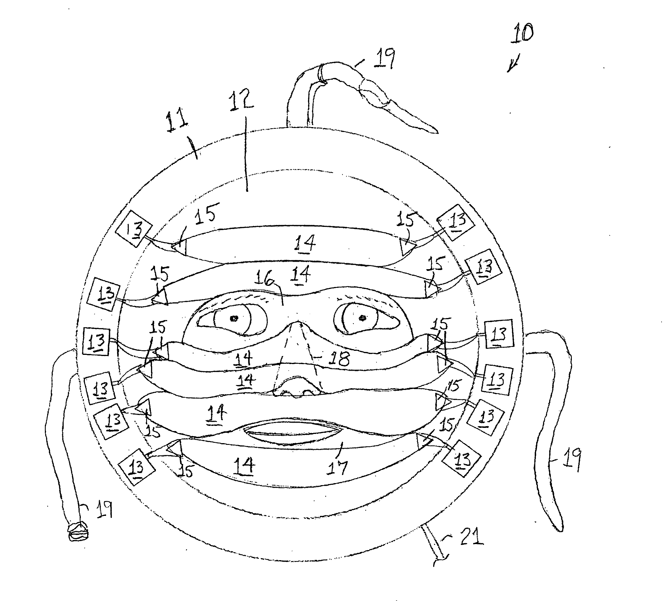
[0034]Referring to FIG. 5, the phototherapy mask representing the preferred embodiment of the present invention 10 comprises a perimeter 11, which is an annular sheet of elastically deformable plastic material that is attached to the circumference of a hub 12, which is a circular, elliptical or oval sheet of flexible, transparent plastic having a refractive index greater than 1.5. Attached to the perimeter 11 are twelve light modules 13, each of which is coupled to one end of one of six fiber-optic bundles 14. Each fiber-optic b...


PUM


Abstract

A phototherapy mask uses optical fibers coupled to LEDs to irradiate a treated epidermal skin area on or around a person's face with specific wavelengths of light in selected dosages (J/cm2). Peripheral configuration of LEDs on the mask eliminates problems of heat dissipation, and multi-mode optical fiber is employed for diffusion of light uniformly over the treated epidermal skin area.

Description

BACKGROUND OF THE INVENTION [0001]The present invention relates to therapeutic devices, and more specifically to devices for administering external light therapy, also known as phototherapy, to organic tissue, and particularly to the epidermal layer of the human skin, in order to treat various medical conditions.[0002]Certain portions of the infrared, visible, and ultraviolet light spectra have proven to provide efficacious treatment for several organic disorders, including, for example, infantile jaundice and seasonal affective disorder. In particular, various skin conditions respond favorably to certain light spectra, including acne, lesions, and broken capillaries. Red / infrared light treatment has been used to reverse epidermal damage and induce production of collagen and elastin in order to restore a more youthful appearance to the skin. Blue / violet light therapy is an efficacious treatment for acne and skin lesions.[0003]Epidermal phototherapy treatments are currently administe...

Claims


Application Information

Patent Timeline
IPC IPC(8): A61N5/06
CPCA61N5/0616A61N2005/063A61N2005/0663A61N2005/0652A61N2005/0659A61N2005/0647
Inventor FRANCIS, STACY
Owner FRANCIS STACY
Why Eureka
Try Eureka