
Two-stage plasma process for converting waste into fuel gas and apparatus therefor

a plasma process and waste gas technology, applied in the direction of combustible gas production, molten salt/metal gasification, soldering apparatus, etc., can solve the problems of high energy consumption of electrical energy, significant electrical energy must be used for dissociation,

Inactive Publication Date: 2011-05-12
PYROGENESIS CANADA INC
View PDF12 Cites 13 Cited by
  • Summary
  • Abstract
  • Description
  • Claims
  • Application Information

AI Technical Summary

Benefits of technology

The present invention proposes a two-stage plasma process for converting waste into fuel gas in a more efficient and clean way than incineration. The first stage involves vitrifying or melting the inorganic components of the waste and partially gasifying the organic components. The second stage involves completing the gasification reactions and cleaning the fuel gas. The plasma energy serves as both the vitrification and activation energy for the gasification reactions. The process produces a high-quality fuel gas that can be used in a gas engine or turbine for production of electricity or in chemical synthesis reactions. The process is efficient and produces minimal emissions.

Problems solved by technology

This means that significant amounts of electrical energy must be used for dissociation.
Electrical energy is an expensive form of energy and it is important to use it as efficiently as possible.

Method used


Image

  • Two-stage plasma process for converting waste into fuel gas and apparatus therefor
  • Two-stage plasma process for converting waste into fuel gas and apparatus therefor
  • Two-stage plasma process for converting waste into fuel gas and apparatus therefor

Examples


Embodiment Construction

[0039]The process of the present invention can be used to process various types of industrial, hazardous or domestic waste in the form of liquids or solids. The solid wastes can be hospital waste, mixed plastics waste, municipal solid waste, automobile shredder residue or the like. The liquid wastes can be spent solvents, used oils, petroleum sludge, municipal water treatment sludge, de-inking sludge or similar liquids. Normally, the waste will comprise organic and inorganic constituents and in most cases, it will be rich in organic materials. When the waste comprises a combination of solids and liquids, the liquid portion should normally not exceed about 30% by weight of the total.

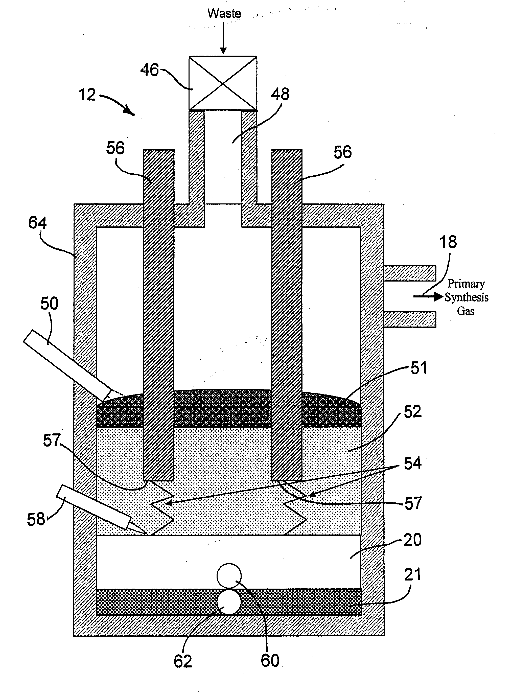
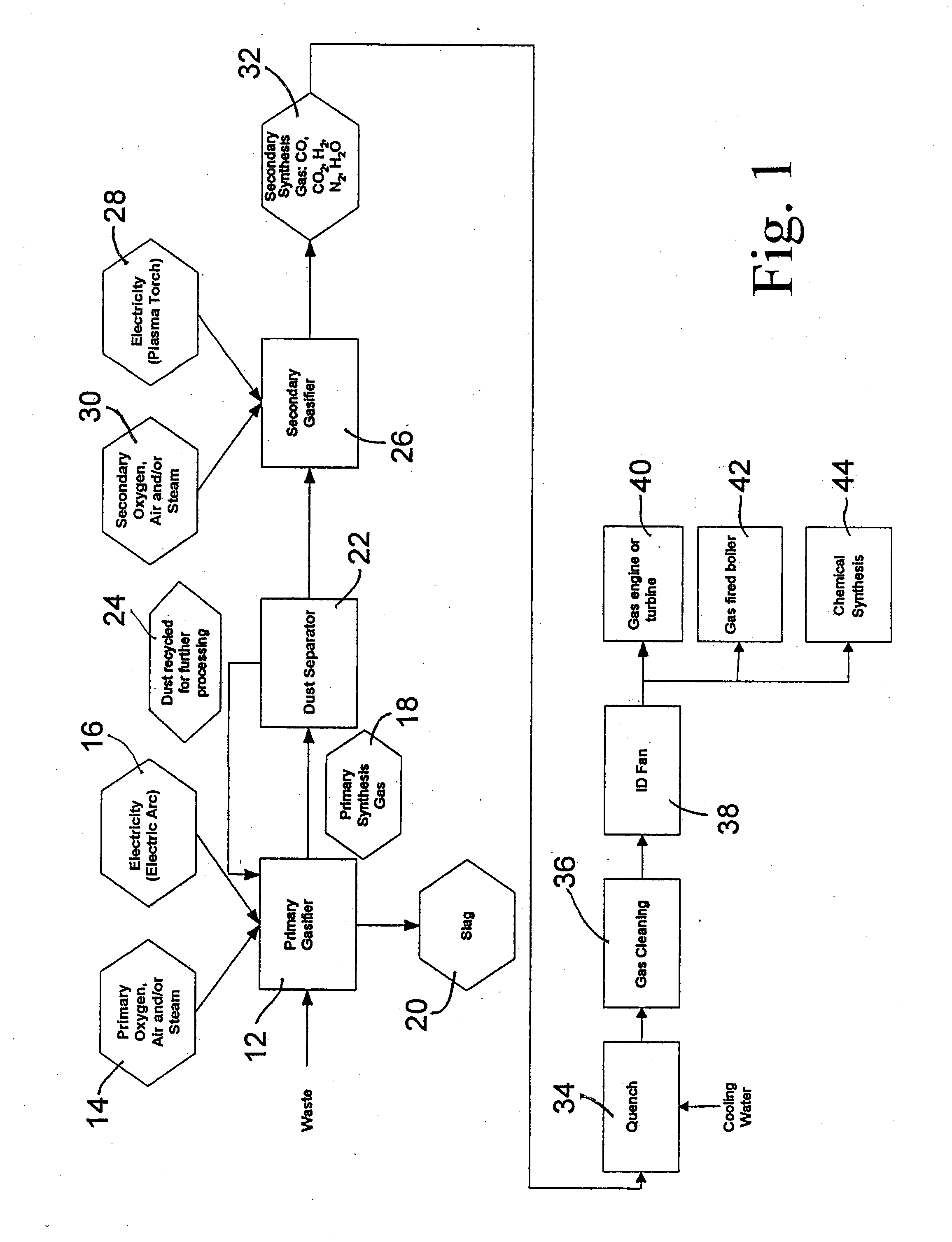
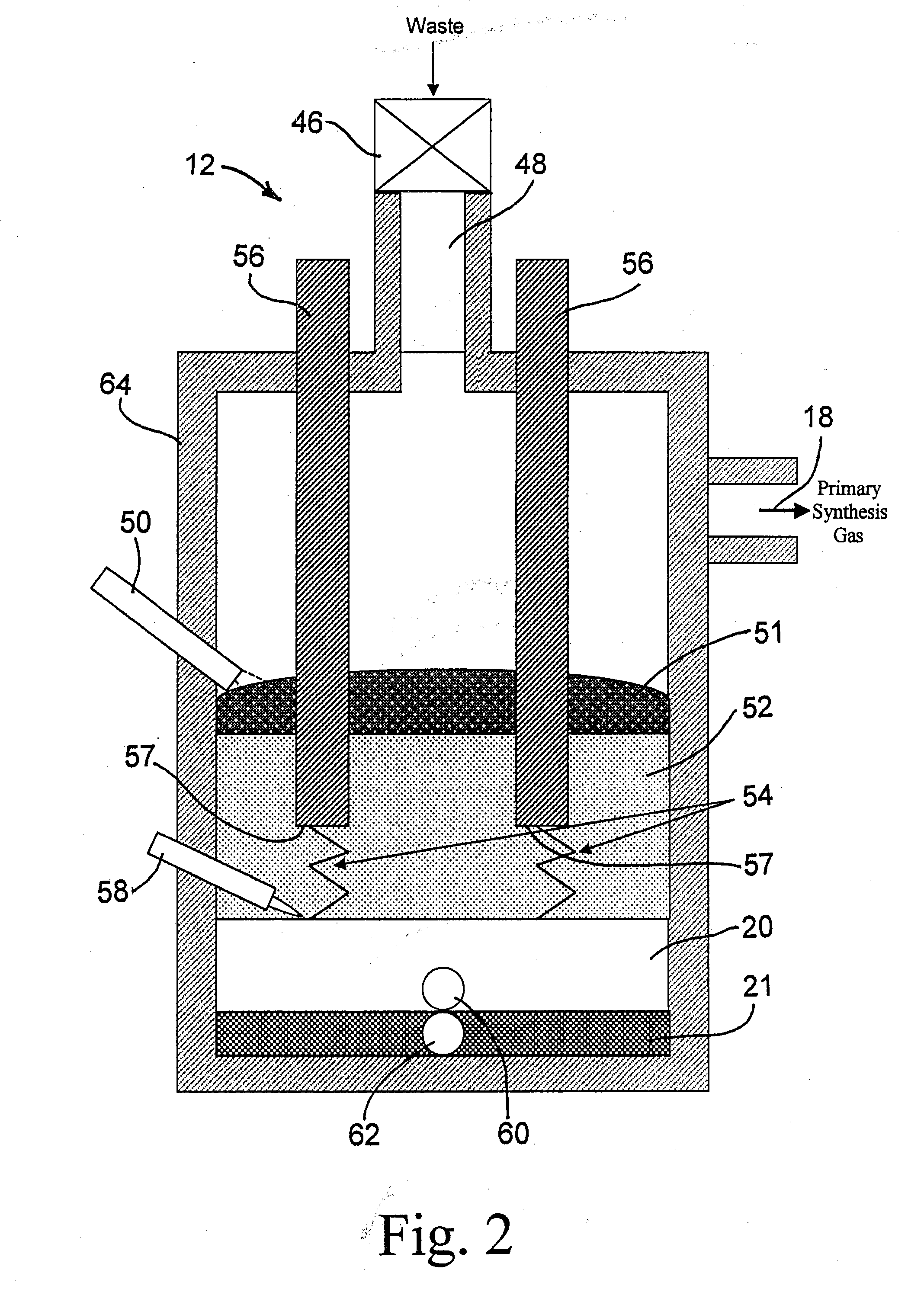
[0040]As shown in FIG. 1, the waste is first introduced into a primary gasifier (12) which is a plasma furnace. This plasma furnace is normally a refractory lined, enclosed, graphite arc furnace, where the plasma is generated by one or several direct current electrodes forming an electric arc, generally a...


PUM

PropertyMeasurementUnit
temperatureaaaaaaaaaa

Abstract

A two-step gasification process and apparatus for the conversion of solid or liquid organic waste into clean fuel, suitable for use in a gas engine or a gas burner, is described. The waste is fed initially into a primary gasifier, which is a graphite arc furnace. Within the primary gasifier, the organic components of the waste are mixed with a predetermined amount of air, oxygen or steam, and converted into volatiles and soot. The volatiles consist mainly of carbon monoxide and hydrogen, and may include a variety of other hydrocarbons and some fly ash. The gas exiting the primary gasifier first passes through a hot cyclone, where some of the soot and most of the fly ash is collected and returned to the primary gasifier. The remaining soot along with the volatile organic compounds is further treated in a secondary gasifier where the soot and the volatile compounds mix with a high temperature plasma jet and a metered amount of air, oxygen or steam, and are converted into a synthesis gas consisting primarily of carbon monoxide and hydrogen. The synthesis gas is then quenched and cleaned to form a clean fuel gas suitable for use in a gas engine or a gas burner. This offers higher thermal efficiency than conventional technology and produces a cleaner fuel than other known alternatives.

Description

BACKGROUND OF THE INVENTION[0001]1. Field of the Invention[0002]The present invention relates to a method and apparatus for a two-stage conversion of organic components contained in solid and / or liquid waste, at high plasma temperature, into a fuel gas suitable for use in a gas engine or turbine for the production of electricity or a gas burner for the production of steam, or in chemical synthesis reactions.[0003]2. Description of the Prior Art[0004]Numerous methods have been proposed for the conversion of waste into energy. The most common method is incineration. In incineration systems, waste is typically introduced in a high temperature chamber and reacted with large amounts of air. The process can be one stage or two stages. Whether the incineration process is one stage or two stages, the process always uses large amounts of air, resulting in the production of large amounts of hot off-gas, typically laden with entrained particulates and acid gas components. Thermal energy is typ...

Claims


Application Information

Patent Timeline
Patent Type & Authority Applications(United States)
IPC IPC(8): C10J3/72C10J3/46C10J3/18C10J3/57
CPCC10J3/18C10J3/466C10J3/57C10J3/721C10J2200/12C10J3/845C10J2300/095C10J2300/1238C10J2300/1634C10J2300/1807C10J2300/094Y02E20/12
Inventor CARABIN, PIERRETSANTRIZOS, PETER GEORGE
Owner PYROGENESIS CANADA INC
Learn More