Semiconductor device and manufacturing method thereof
a technology of semiconductor devices and manufacturing methods, applied in semiconductor devices, semiconductor/solid-state device details, electrical apparatus, etc., can solve the problems of increased manufacturing cost, low dopant activation ratio, and inability to process at high temperature, and achieves the effect of reducing manufacturing costs, reducing manufacturing costs, and mechanical strength of wafers
- Summary
- Abstract
- Description
- Claims
- Application Information
AI Technical Summary
Benefits of technology
Problems solved by technology
Method used
Image
Examples
example 1
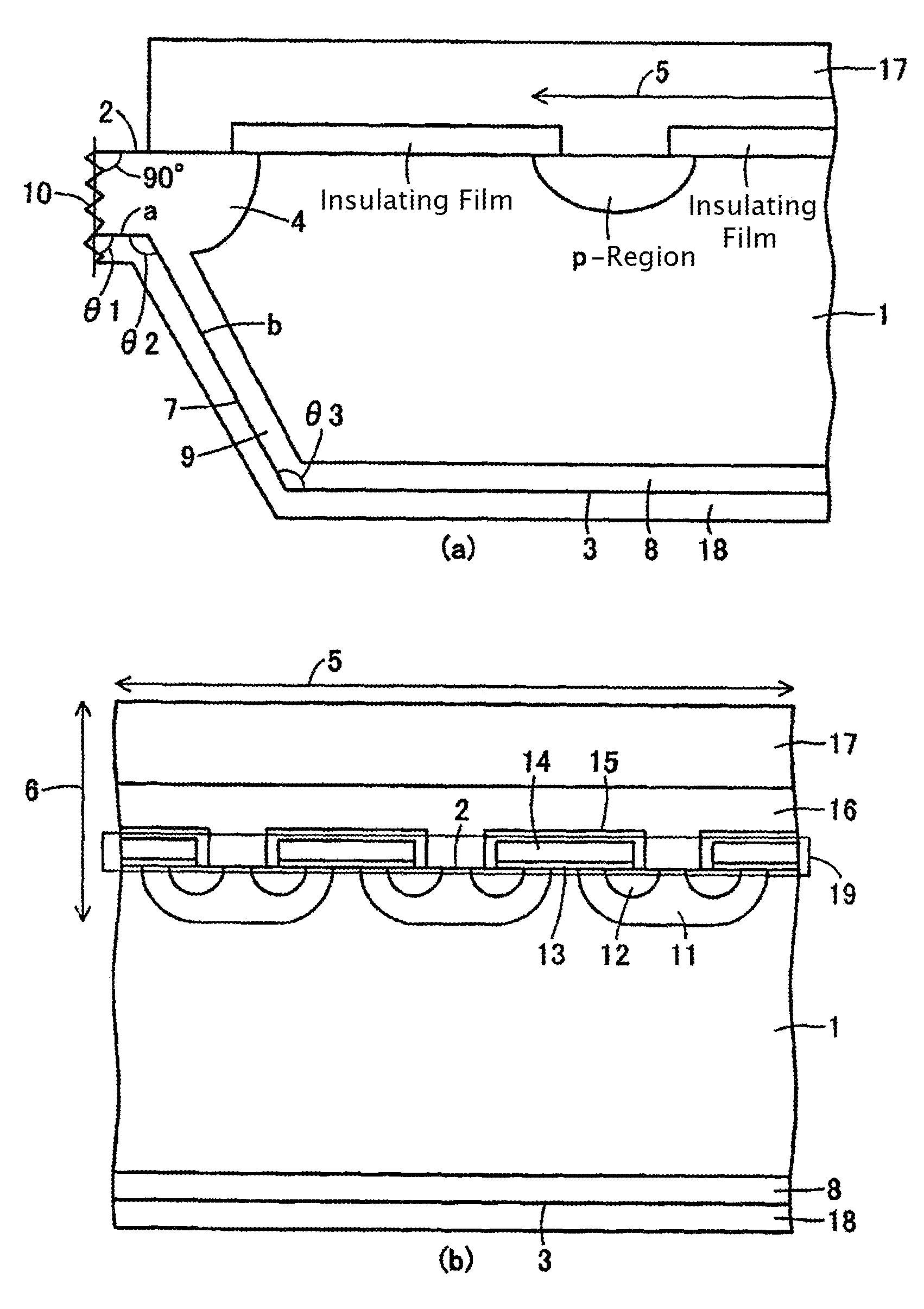
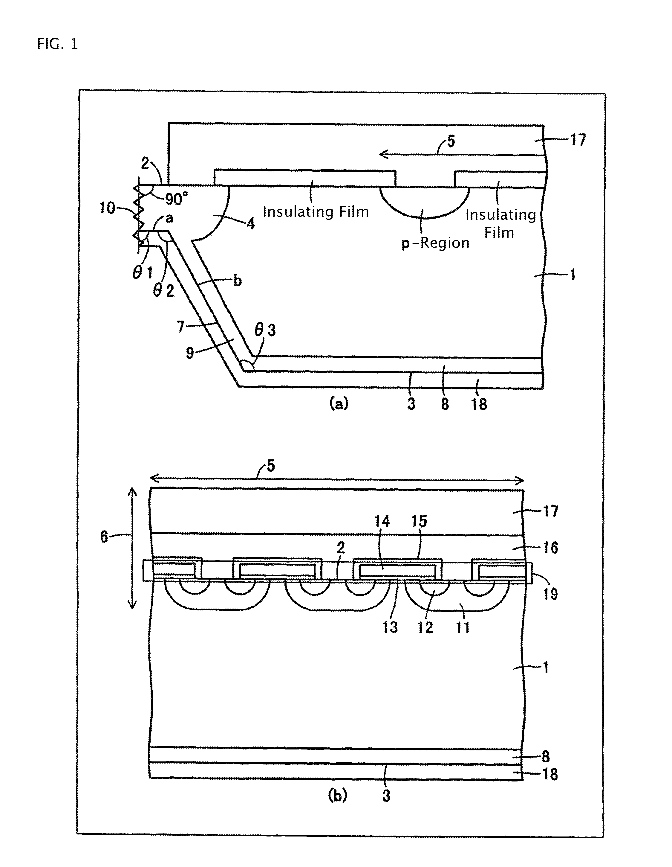
FIG. 1 is a cross-sectional view of a semiconductor device according to Example 1 of the present invention, where FIG. 1(a) is a cross-sectional view of a key portion near a p-isolation layer, and FIG. 1(b) is a cross-sectional view of a key portion of an active region. For this semiconductor device, a reverse blocking IGBT is described as an example. This reverse blocking IGBT comprises: an n-semiconductor substrate 1; a p-diffusion layer 4 which is formed on an outer periphery portion of the surface of a first principal plane 2 of the n-semiconductor substrate 1; a device surface structure 6 which is formed on a surface layer of an active region 5 (region where main current flows) of a first principal plane 2 (front face) of the n-semiconductor substrate 1 so as to be enclosed by the p-diffusion layer 4, isolated from the p-diffusion layer 4; a p-collector layer 8 which is formed on the surface layer of a second principal plane 3; a collector electrode 18 which is formed on the p-...
example 2
FIG. 12 is manufacturing process drawings depicting a method for manufacturing a semiconductor device of Example 2 of the present invention, where FIG. 12(a) is a plan view of the wafer, FIG. 12(b) is a cross-sectional view of a key portion sectioned at the X1-X1 line in FIG. 12(a), FIG. 12(c) is a cross-sectional view of a key portion sectioned at the X2-X2 line in FIG. 12(a), and FIG. 12(d) is a cross-sectional view of a key portion sectioned at the Y-Y line in FIG. 12(a). The dotted line in FIG. 12(d) indicates the thickness of the wafer 40 in a portion where the grooves 41 are not formed. FIG. 12 shows the processes of forming the grooves 41, in the case of the depth of the groove 41 is decreased in the outer periphery portion 44 of the wafer 40. The grooves 41 are formed all the way to the outer edge 45 of the wafer 40.
By forming the groove 41 to be shallower in the outer periphery portion 44 of the wafer 40, the film thickness of the residual film 43 becomes thicker closer to ...
example 3
FIG. 13 is manufacturing process drawings depicting a method for manufacturing a semiconductor device of Example 3 of the present invention, where FIG. 13(a) is a plan view of a process of a key portion of the wafer, and FIG. 13(b) is a cross-sectional view of a process of a key portion sectioned at the Y-Y line in FIG. 13(a). The dotted line in FIG. 13(b) indicates the thickness of the wafer 40 in a portion where the groove 41 is not formed. FIG. 13 shows the processes of forming the grooves 41, in the case where the depth of the groove 41 is decreased in an area away from the chip forming region 42, so that a part of the groove 41 does not reach the outer edge 45 of the wafer 40.
This makes the thickness of the residual film 43 in the outer periphery portion 44 thicker than the case of FIG. 12, so the wafer 40 is even less likely to be cracked than the case of FIG. 12. Further, an increase of the mechanical strength makes handling of the wager 40 even easier.
PUM
 Abstract
Description
Claims
Application Information
 - R&D
- Intellectual Property
- Life Sciences
- Materials
- Tech Scout
- Unparalleled Data Quality
- Higher Quality Content
- 60% Fewer Hallucinations
Browse by: Latest US Patents, China's latest patents, Technical Efficacy Thesaurus, Application Domain, Technology Topic, Popular Technical Reports.
© 2025 PatSnap. All rights reserved.Legal|Privacy policy|Modern Slavery Act Transparency Statement|Sitemap|About US| Contact US: help@patsnap.com


