Liquid-phase chemical looping energy generator

a technology of energy generator and liquid phase, which is applied in the direction of arsenic compounds, lighting and heating apparatus, gas-gas reaction processes, etc., can solve the problems of reducing the overall combustion efficiency of the step, generating or consuming heat, and releasing hea

Active Publication Date: 2011-05-19
PHILLIPS 66 CO
View PDF14 Cites 34 Cited by
  • Summary
  • Abstract
  • Description
  • Claims
  • Application Information

AI Technical Summary

Problems solved by technology

Depending on the materials and fuels, this step may generate or consume heat.
In conventional CLC, this step always results in the release of heat.
Unfortunately these clean combustion methods require large supplemental energy for CO2 capture greatly reducing their overall combustion efficiency.
The main problem with solid oxygen carriers is that they undergo mechanical degradation while being cycled from a reduced state to an oxidized state over and over again, from attrition, erosion, fatigue, crystalline changes, irreversible and side reactions, etc.
The result is that the solid carriers turn into ever finer particles, making moving and managing solids quite difficult, and making the useful lifetime of the oxygen carriers uneconomically short.
Moreover, continuously moving hot solid particles from one reactor to another is complicated.
In addition to mechanical degradation, chemical degradation of the solid oxygen carrier also occurs with each cycle, such that the fraction of the total oxygen carrier available to take part in chemical reactions continuously decreases with use.

Method used


Image

  • Liquid-phase chemical looping energy generator
  • Liquid-phase chemical looping energy generator
  • Liquid-phase chemical looping energy generator

Examples


example 1

Molybdenum Oxide Reaction

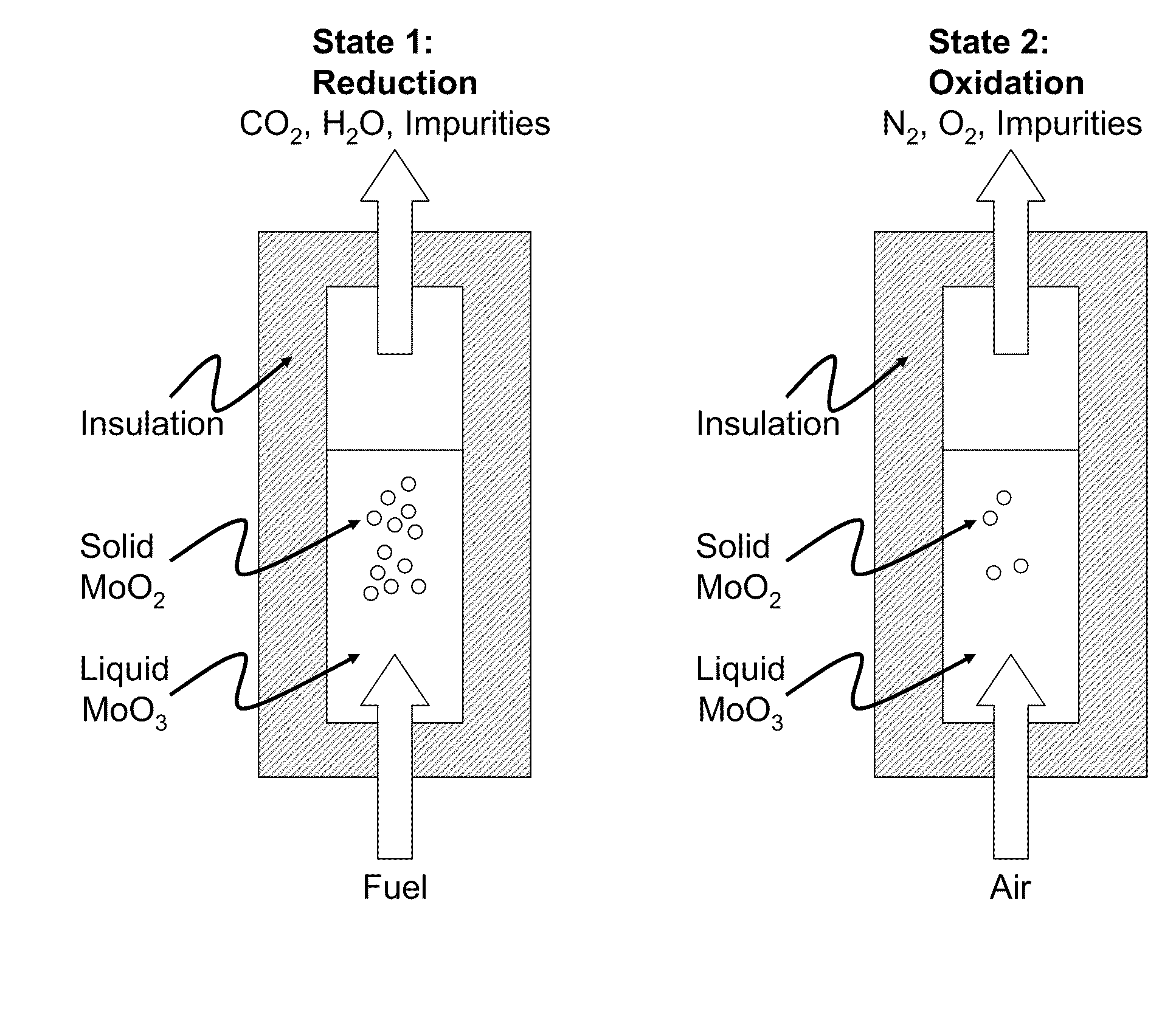
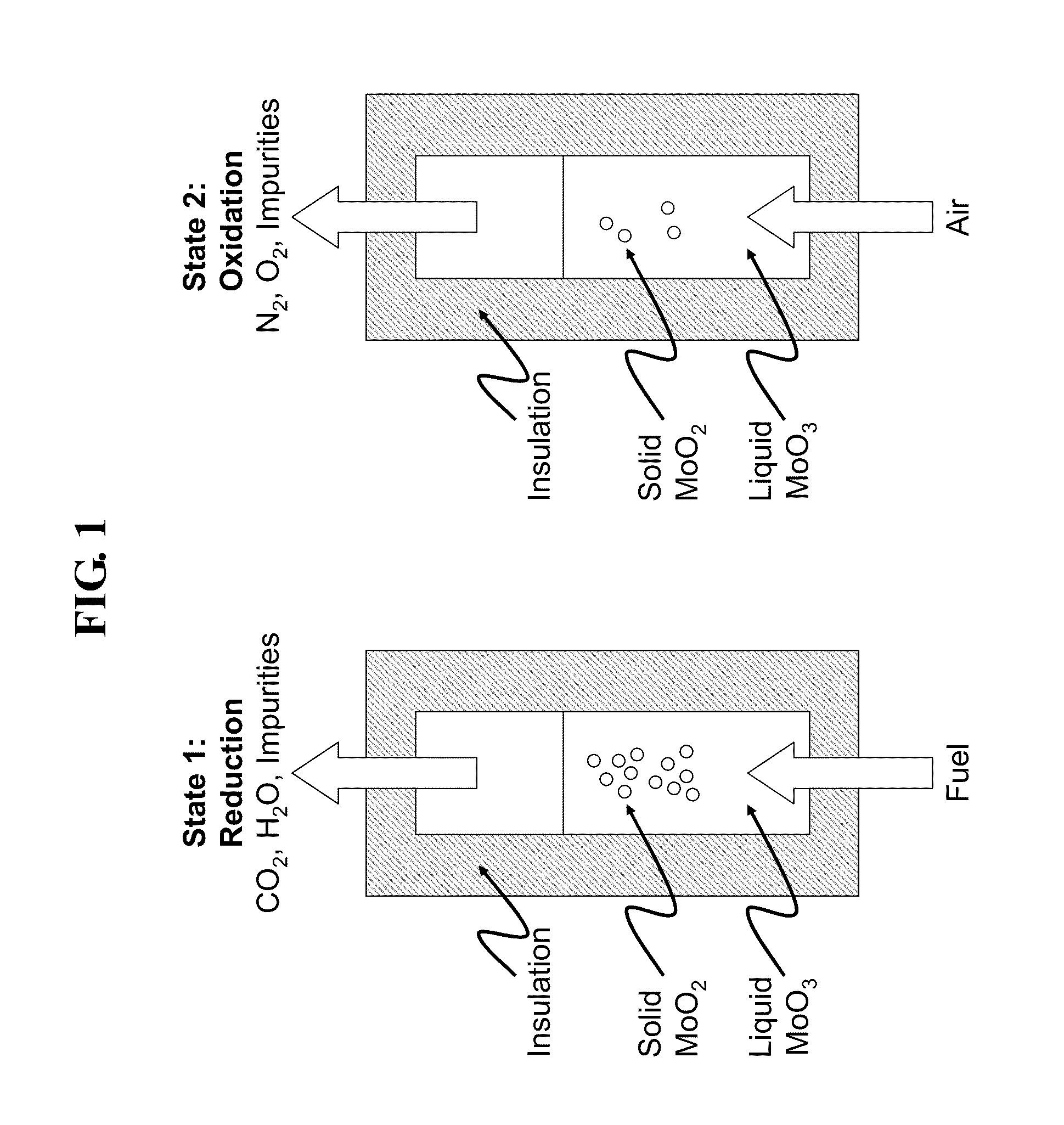
[0023]In one embodiment a desirable metal oxide would be MoO3. MoO3 has a sufficiently low melting point of approximately 795° C. that conventional reactor materials with standard construction and care may be used to contain the reaction. Assuming the carbonaceous fuel to be pure carbon, the reaction chemistry is as follows:

TABLE 2Molybdenum Oxide CLC reactionsRxn. TypeRxn. StoichiometryStd. Rxn. EnthalpyFuel Oxidation2 MoO3 + C = 2 MoO2 + CO2 −82.9 MJ / mol carbonOxide2MoO2 + O2 = 2 MoO3−310.6 MJ / mol O2RegenerationNetC + O2 = CO2−393.5 MJ / mol

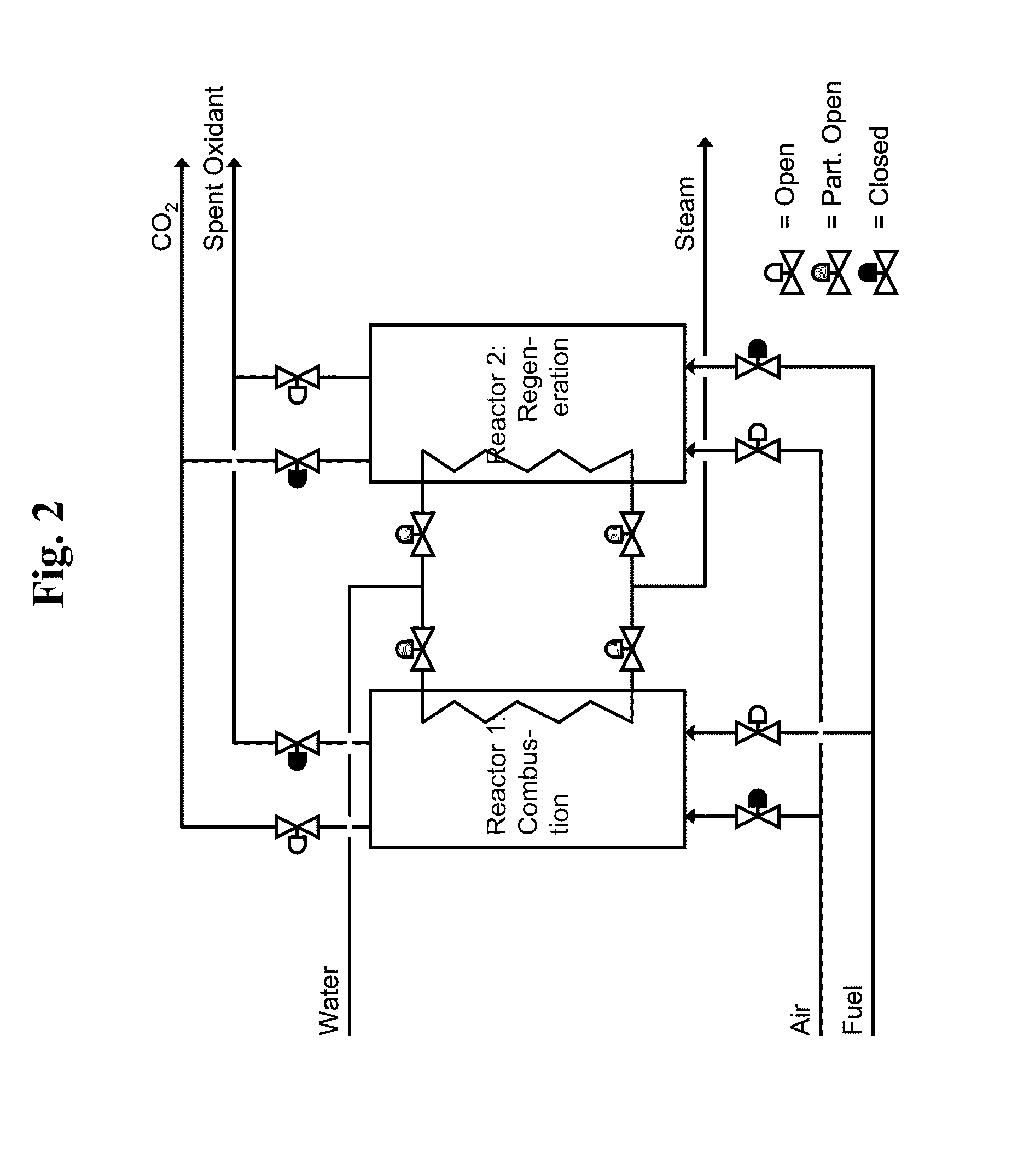
[0024]A reactor contains a pool of molten MoO3 in direct or indirect thermal contact with a closed-loop steam system and a heat recovery system to recover useful heat from the exiting exhaust and regeneration gas streams. In addition, the reactor would also be in contact with a CO2 capture system that captures and prepares the CO2 released from fuel combustion with MoO3 for disposal. The reactor would ideally be operated ...

example 2

Blended Metal Oxides

[0025]Metal oxides including molybdenum, vanadium, manganese, copper, and bismuth oxides may be blended. These metal oxides may also be blended with other oxides such as boric oxide, lime and other materials, to change the overall melt temperature, change the upper or lower temperatures of the reaction, and generally to obtain desirable properties of the bulk melt. Refractory materials for the reaction chamber are widely available and include materials such as silicon carbide, chromia, alumina, magnesia, dolomite or combinations. An extensive, but not exhaustive, list of metal oxides that are useful for the refractory, melt, or as a oxide catalyst are listed in Table 3. More strongly ionic species such as nitrate, phosphate, silicate and sulfate metallic salts, are not shown, but could also be used in varying amounts in the melt.

TABLE 3Metal SpeciesMeltingMeltingPointPrimaryMetalPoint[° C.]UseOxide[° C.]Primary UseGroup IALi186n / aLi2O1,570MeltNa98n / aNa2O1,132Melt...


PUM

PropertyMeasurementUnit
melting pointaaaaaaaaaa
combustion efficiencyaaaaaaaaaa
electricalaaaaaaaaaa

Abstract

A closed loop combustion system for the combustion of fuels using a molten metal oxide bed.

Description

CROSS REFERENCE TO RELATED APPLICATIONS[0001]This application is a non-provisional application which claims benefit under 35 USC §119(e) to U.S. Provisional Application Ser. No. 61 / 262,774 filed Nov. 19, 2009, entitled “LIQUID-PHASE CHEMICAL LOOPING ENERGY GENERATOR,” which is incorporated herein in its entirety.STATEMENT OF FEDERALLY SPONSORED RESEARCH[0002]None.FIELD OF THE DISCLOSURE[0003]The present disclosure generally relates to methods and apparatus for chemical looping combustion, particularly to a molten metal oxide catalyst for chemical looping combustion.BACKGROUND OF THE DISCLOSURE[0004]Chemical looping combustion (CLC) is generally characterized by 2 fundamental stages. In the first stage a solid material, typically desirably sized solid particles of metal oxide, are contacted with a carbon containing fuel such that the metal oxide gives up its oxygen to the fuel, forming carbon dioxide and a reduced state material. Depending on the materials and fuels, this step may ge...

Claims


Application Information

Patent Timeline
Patent Type & Authority Applications(United States)
IPC IPC(8): C01B31/20C01G31/02C01G45/02C01G3/02C01G39/02C01G29/00B01J19/00C01B32/50
CPCC01G3/02C01G29/00C01G31/02Y02E20/346C01G45/02F23C2900/99008B01J10/005C01G39/02Y02E20/34
Inventor LAMONT, DAVID C.SEABA, JAMESLATIMER, EDWARD G.PLATON, ALEXANDRU
Owner PHILLIPS 66 CO
Why Eureka
Try Eureka