
Electrode for electrochemical cells

a technology of electrochemical cells and electrodes, applied in the field of electrochemical cells, can solve the problems of rapid diminution of the catalytic effect, high price of platinum, and complex construction of fuel cells, and achieve the effect of avoiding degradation or deterioration of performan

Inactive Publication Date: 2011-05-19
MONASH UNIV
View PDF12 Cites 13 Cited by
  • Summary
  • Abstract
  • Description
  • Claims
  • Application Information

AI Technical Summary

Benefits of technology

[0031]Various additives may be added to optimise the electrolyte characteristics. For example, additives may be chosen from the group comprising solvents that act as ‘swelling agents’, non-solvents, ionic-liquids and phosphates. The role of these additives is to enhance the interaction between the electrolyte and the conducting polymer, that is, to help optimise the three phase interface. For example, the additives may improve the structure of the conducting polymer by causing it to swell.Anode
[0046]The electrode of the present invention may contain one or more ICPs. For example, the electrode may include two or more ICPs in a physical mixture or a layered structure or an interpenetrating network. Furthermore, the ICP for use in the present invention may comprise one or more ICPs in combination with one or more non-conducting polymers. The combination of non-conducting polymer and ICP may provide characteristics that are preferable to the characteristics of the ICP alone. For example, a non-conducting polymer based on polyethylene glycol (PEG) may be added to provide improved hydrophilicity, phase interface, current density or theological characteristics compared with the pure ICP.Combination of Porous Organic Material and ICP
[0049]A cell having an air / Goretex® / PEDOT cathode and magnesium anode has demonstrated continues operation for 3 weeks without degradation or deterioration of performance. PEDOT also has the advantage of being stable over a wide pH range (pH 0 to 14). The PEDOT appears to cycle its oxidation state during the oxygen reduction reaction. This has been demonstrated in two different modes (1) as an electrode operating at ambient pressure and (2) as a dissolved oxygen electrode operating in aqueous solutions.
[0059]The electrochemical cell according to the present invention may comprise a battery that provides a direct current (DC). However by combining two batteries appropriately wired, and switching between the two, it is possible to provide an alternating current (AC). This would be particularly advantageous for many in-vivo applications where the use of DC causes damaged caused by electrophoresis
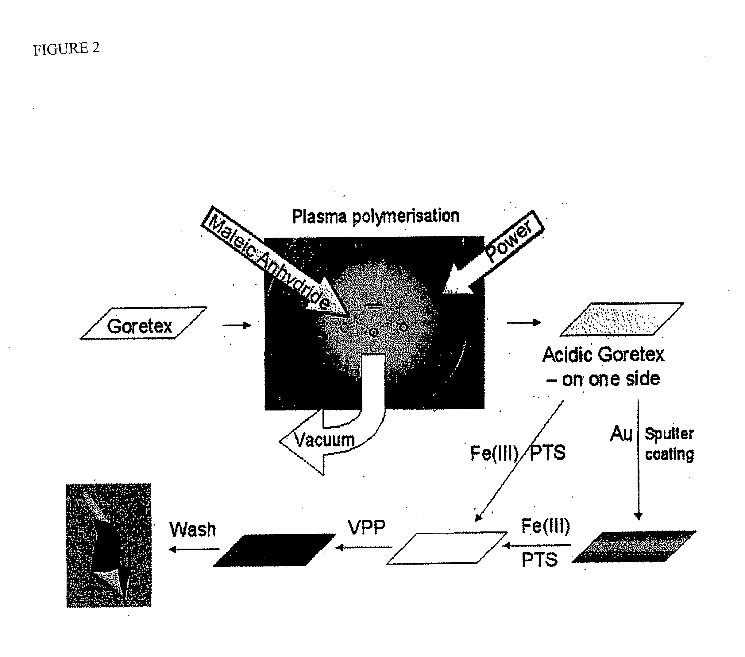
[0081]In Examples 1 and 5, Fe(III) PTS is described for applying the ICP to a porous organic material. Fe(III)CI is much cheaper than Fe(III) PTS, but it has not hitherto been possible to obtain smooth and homogeneous coatings when using Fe(III)CI as oxidant for polymerisation of conducting polymers. As described in Example 5, coating onto PE and PVDF membranes without coating through them forced a change in solvent for the Fe(III) solution from the traditional alcohol based to a mainly water-based system. By adding a small amount of additives to the solution in form of oligo-polyurethanes, poly-ethyleneglycol (PEG) or similar hydrophilic molecules it was possible to obtain smooth films of the dried Fe(III)CI and the subsequent vapour phase polymerisation also produced PEDOT film with good smoothness. When studied in the scanning electron microscope (SEM) it was found that these PEDOT-CI coatings are nano-structured. Controlling the nano-structure of the PEDOT material itself can have big advantages in order to increase active surface area and minimize diffusion limitations in the material. The properties of the nano-structure (such as size and hydrophilicity) can be varied by changing the kind and amount of additives.

Problems solved by technology

However a battery typically holds a limited fuel supply in a sealed container whereas a fuel cell uses an ongoing supply of fuel to create a continuous flow of electricity.
One of the problems associated with fuel cells is that platinum is expensive and the construction of fuel cells is typically complex.
Furthermore, these cells suffer from problems including drifting of the particles of platinum catalyst leading to significant, rapid diminution of the catalytic effect.

Method used


Image

  • Electrode for electrochemical cells
  • Electrode for electrochemical cells
  • Electrode for electrochemical cells

Examples


example 1

PEDOT on Goretex

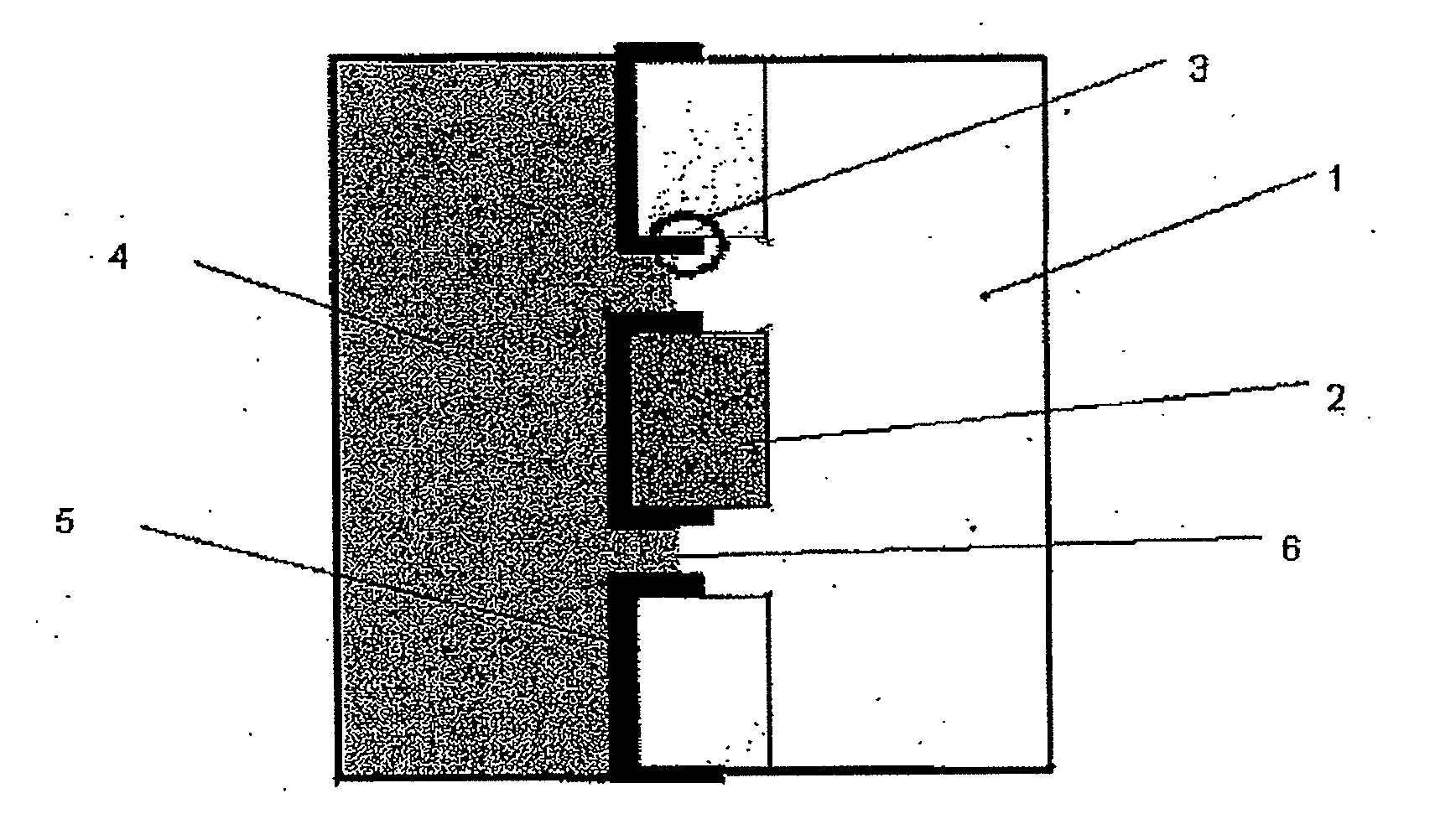
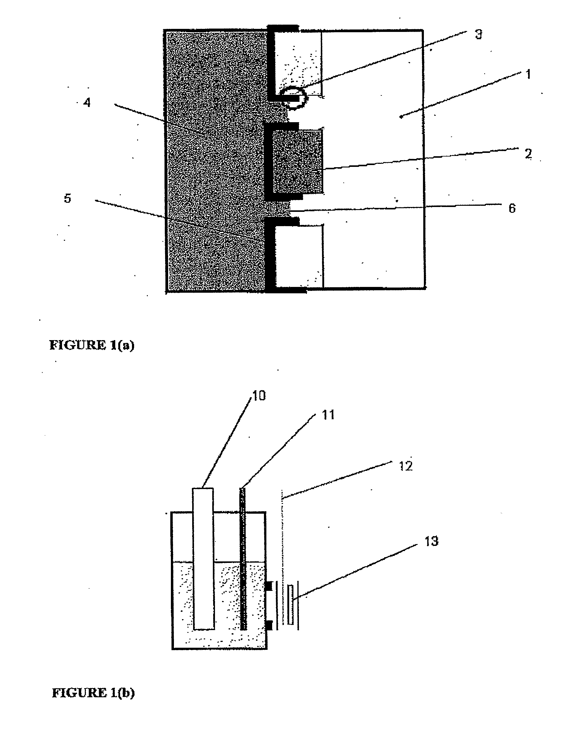
[0062]One embodiment of an electrode for the con of the present invention is depicted schematically in FIG. 1(a). The electrode was then included in an electrochemical cell of the type depicted at FIG. 2(e) and used in a series of experiments to characterise the present invention and compare its performance with more conventional constructions in some of the experiments the electrode also includes a thin layer (approx. 20 nm) of gold between the ICP and Goretex, the gold acting as a conductor. The results of these tests are depicted in FIGS. 3 to 10. The electrolyte used for each test is as specified below.

[0063]The electrode as depleted in FIG. 1 allows access of the air stream from one side of the electrode to a high-surface area electrochemically active layer of ICP which is simultaneously in contact with electrolyte. The structure of the underlying porous material is visible in the electrode indicating that a three-phase boundary interface is obtained over a subs...

example 2

PEDOT on Goretex in an H2 / O2 Fuel Cell

[0068]The PEDOT-Au-Goretex electrode described above was also used in a hydrogen / oxygen fuel cell comprising a Nafion polymer membrane. The electrode was used to replace the usual carbon / Pt cathode in the cell construction, so the carbon / Pt anode for hydrogen oxidation and the proton-conducting polymer membrane (Nafion®) was unchanged. The cell was placed in a graphite setup, ensuring good electrical and thermal contact. The humidity and the temperature of the cell were controlled during the test.

[0069]This fuel cell was used to generate the plot shown as FIG. 10 below. The discharge current was stepped up to 100□A / cm2 and the voltage measured over time, while hydrogen and oxygen was supplied to the cell with constant flow-rates.

example 3

Example 3(a)

PEDOT on Au and Au / Pt Coated Goretex

[0070]A PEDOT Au-Goretex electrode Was compared with a PEDOT-Au / Pt-Goretex electrode at different pH values. The latter was created by sputtering a 45 nm Pt layer onto the Au layer. The thickness of the Pt was measured on a glass slide exposed to same Pt sputter procedure.

[0071]The magnitudes of the conversion currents delivered by the PEDOT electrode are comparable to those of Pt for the same geometrical area of porous material. However, as seen in FIGS. 4(a) to 4(c), at low pH the platinum based electrode is more efficient whereas at higher pH the conversion currents are similar. Most proton conducting polymer membrane fuel-cells are operated at low pH.

[0072]Although the thicknesses are different for the Pt (45 nm) and PEDOT (400 nm) layers the differences in their densities (21.1 g / cm3 for Pt and approx 1.2 g / cm3 for PEDOT) means that the mass loading of active material is actually lower in the PEDOT case by a factor of about 2.

Exam...


PUM

PropertyMeasurementUnit
Currentaaaaaaaaaa
Electrical conductoraaaaaaaaaa
Charge transfer stateaaaaaaaaaa

Abstract

The invention relates to an electrode for oxygen reduction comprising a porous organic material and at least one inherently conducting polymer such as a charge transfer complex or a conductive polymer, optionally combined with a non-conducting polymer. A current conductor may be located intermediate the porous organic material and the inherently conductive polymer. The electrode is suitable for use with an ion-conducting membrane and fuel such as hydrogen, an alcohol or borohydride to form a fuel-cell. The electrode is also suitable for use with an anode, such as a reactive metal and an electrolyte to form a battery.

Description

FIELD OF THE INVENTION[0001]This Invention relates to electrochemical cells such as batteries and fuel cells. Even more particularly the present invention relates to electrochemical cells having a metal or catalytically active anode and an electrode comprising an inherently conducting polymer.BACKGROUND OF THE INVENTION[0002]In this specification where a document, act or item of knowledge is referred to or discussed, this reference or discussion is not an admission that the document, act or Item of knowledge or any combination thereof was at the priority date, publicly available, known to the public, part of common general knowledge; or known to be relevant to an attempt to solve any problem with which this specification is concerned.[0003]While the present invention will be principally described with reference to use of a magnesium metal anode or an active catalytic platinum anode it will be readily appreciated that the present invention is not so limited, but can be extended elect...

Claims


Application Information

Patent Timeline
IPC IPC(8): H01M4/60H01M4/52H01M4/58H01M2/02H01B1/12H01B1/02H01B1/04C23C16/44C23C16/50B05D5/12
CPCH01B1/122Y02E60/13H01M4/382H01M4/405H01M4/42H01M4/463H01M4/466H01M4/60H01M4/606H01M4/608H01M4/621H01M4/622H01M4/8605H01M4/9008H01M8/1011H01M8/22H01M12/06H01M2004/8689H01M2008/1095Y02E60/523H01G11/30H01G11/48Y02E60/522H01M4/38Y02E60/10Y02E60/50
Inventor WINTHER-JENSEN, BJORNFORSYTH, MARIAMACFARLANE, DOUGLAS ROBERT
Owner MONASH UNIV
Learn More