Dust removing device and dust removing method

a technology of dust removal device and dust removal method, which is applied in the direction of mechanical vibration separation, cleaning using liquids, camera filters, etc., can solve the problems of the length vibration to be generated in the piezoelectric device, and the inability to realize lead-free material having various properties equivalent to those of pzt, etc., to achieve high dust removal performance, easy to fix, and efficiently utilize the displacement capability inherent in

Inactive Publication Date: 2011-05-26
CANON KK
View PDF36 Cites 12 Cited by
  • Summary
  • Abstract
  • Description
  • Claims
  • Application Information

AI Technical Summary

Benefits of technology

[0021]The present invention has been made in view of the above, and therefore has an object to provide a dust removing device which is easy to fix and a dust removing method, which are capable of efficiently utilizing a displacement capability inherent in a piezoelectric device and achieving high dust removal performance.
[0024]According to the present invention, there may be provided a dust removing device which is easy to fix and a dust removing method, which are capable of efficiently utilizing a displacement capability inherent in the piezoelectric device and achieving high dust removal performance.
[0025]In particular, in a case where the piezoelectric device is in a rectangular solid shape, the wavefront of the flexural vibration generated in the vibrating plate may be easily formed with an equal amplitude, and hence there may be provided a dust removing device and a dust removing method having a higher dust removal performance.

Problems solved by technology

In particular, in a single-lens reflex digital camera which includes an interchangeable lens, dust may enter the digital camera main body through the opening of the lens mount when the lens is being changed, and may adhere to the surfaces of the cover glass of the image pickup element or of the filters.
However, it has been pointed out that such a piezoelectric material made of PZT containing a large amount of lead can be detrimental to ecosystems because the lead component in the piezoelectric material seeps into soil when the piezoelectric material is once discarded to be exposed to acid rain, for example.
However, a lead-free material having various properties equivalent to those of PZT has not been realized, and there are still only a few examples of commercialized devices using a lead-free piezoelectric material which is equivalent in quality to PZT.
However, the vibration to be generated in the piezoelectric device is a length vibration, and hence the dust removing device cannot be directly fixed to the image pickup element or to the digital camera main body.
However, the vibrating plate is subjected to the flexural vibration and the piezoelectric device itself is subjected to the length vibration, the dust removing device cannot be held without inevitably hindering the vibration of the vibrating plate, no matter where the dust removing device is held by the pressing member or the holding member.
Accordingly, according to the conventional configuration of the dust removing device, there has been a problem that the dust removal performance is degraded when the dust removing device is held and fixed to an image pickup element or a digital camera main body.
In other words, in the conventional dust removing device using the length vibration of the piezoelectric device, there has been a problem that the displacement capability inherent in the piezoelectric device cannot be used effectively.
However, the length vibration to be generated in the piezoelectric device occurs omnidirectionally in the length direction of the piezoelectric device, and hence the same wavefront with an equal amplitude may be difficult to form on the vibrating plate.
Accordingly, according to the conventional dust removing device, there has been a problem that the dust removal performance greatly varies depending on the area on the vibrating plate.

Method used


Image

  • Dust removing device and dust removing method
  • Dust removing device and dust removing method
  • Dust removing device and dust removing method

Examples


example 1

[0095]In the following, the dust removing device of the present invention is specifically described with reference to Examples. However, the present invention is not limited by the following Examples.

[0096]First, a method of manufacturing the piezoelectric device of the present invention is described. Barium titanate particles with an average particle diameter of 100 nm (manufactured by Sakai Chemical Industry Co., Ltd., BT-03 as a trade name) were coated with manganese acetate (II) by using a spray dryer. According to inductively coupled plasma (ICP) mass spectrometry, the powder mix had a manganese content of 0.12% by mass.

[0097]Next, the powder mix was added with a polyvinyl alcohol aqueous solution at a concentration of 5% by mass, as a dispersant. The additive amount was determined so that polyvinyl alcohol in the polyvinyl alcohol aqueous solution was 3% by mass with respect to the powder mix. The mixture was mixed in a mortar, to thereby manufacture a granulated powder mix. T...

example 2

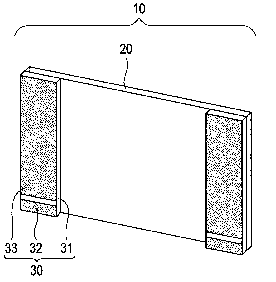
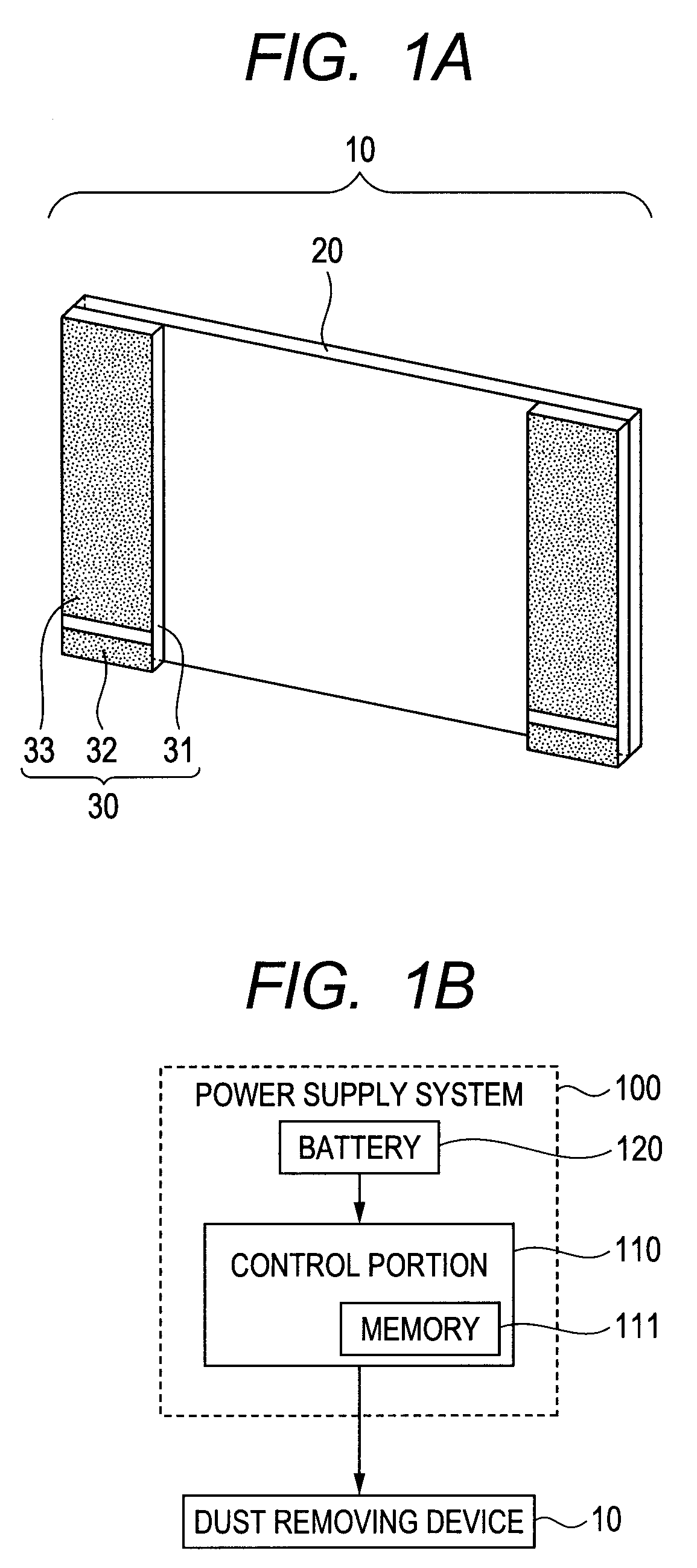
[0104]By using a method similar to that of Example 1, the dust removing device of Example 2 of the present invention was formed similarly to Example 1, except in that the two piezoelectric devices of the present invention were further provided, as illustrated in FIG. 1A, along both sides of 33.7 mm of a glass plate having a function of an infrared cut filter. The two piezoelectric devices were disposed so that the polarization directions were opposed to each other.

[0105]In order to confirm the effect of Example 2, frequency response calculation based on a finite element method was performed in a range from 125 kHz to 145 kHz, on conditions similar to those of Example 1, except in that the restraint conditions were provided as (1) the second electrode planes of the two piezoelectric devices were fixed, (2) the piezoelectric device was applied with a voltage of 10 V across the upper surface and the lower surface, and (3) the two piezoelectric devices were applied with voltages in the ...

example 3

[0111]As illustrated in FIG. 15, a flexible wiring cable 90 was bonded through a conductive epoxy resin adhesive to a part of the second electrode plane of the piezoelectric device forming the dust removing device of Example 2, so as to allow a voltage to be applied thereto from a power supply via the flexible wiring cable 90. Next, the dust removing device configured as described above was fixed, through the second electrode plane of the piezoelectric device, to a stainless-steel support member, along with the portion of the flexible wiring cable being in contact with the piezoelectric device. Further, an alternating voltage of 15 Vpp was applied to the first electrode and the second electrode of the piezoelectric device via the flexible wiring cable from a power supply, to thereby manufacture a dust removing device unit capable of repeatedly vibrating in a 17th order vibration mode and in an 18th order vibration mode. Various plastic beads for evaluating the dust removal rate were...


PUM


Abstract

In a piezoelectric device, a first electrode and a second electrode are disposed to be opposed to each other on plate surfaces of the piezoelectric device, a first electrode plane of the piezoelectric device is fixedly bonded to a plate surface of a vibrating plate, a piezoelectric material forming the piezoelectric device is polarized in a direction parallel to the first electrode plane, the piezoelectric device is fixed to a base through a second electrode plane of the piezoelectric device, and the piezoelectric device generates a thickness-shear vibration with the fixed second electrode plane being a reference plane. The piezoelectric vibration generated by the piezoelectric device generates a flexural vibration in the vibrating plate, to thereby remove dust adhering to a surface of the vibrating plate.

Description

BACKGROUND OF THE INVENTION[0001]1. Field of the Invention[0002]The present invention relates to a technology of removing dust adhering to a surface of an image pickup device such as a digital camera and an optical component incorporated in the image pickup device, and more particularly, to a dust removing device and a dust removing method for removing dust through application of vibration.[0003]2. Description of the Related Art[0004]In an image pickup device such as a digital camera for picking up an image by converting an image signal into an electric signal, a photographing light flux is received by an image pickup element such as a charge coupled device (CCD) or a complementary metal oxide semiconductor (CMOS). Then, a photoelectric conversion signal output from the image pickup element is converted into image data, and the image data is recorded on a recording medium such as a memory card. In such an image pickup device, an optical low-pass filter and an infrared cut filter are...

Claims


Application Information

Patent Timeline
Patent Type & Authority Applications(United States)
IPC IPC(8): F28G7/00
CPCB06B1/0648G02B27/0006G03B11/00H04N5/2254G03B17/14H04N5/2171G03B17/02H04N23/811H04N23/52B08B7/02
Inventor IFUKU, TOSHIHIROFURUTA, TATSUOSAITO, HIROSHITAKEDA, KENICHI
Owner CANON KK
Why Eureka
Try Eureka