Eureka AIR delivers breakthrough ideas for toughest innovation challenges, trusted by R&D personnel around the world.

Water desalination apparatus and method

a technology of desalination apparatus and water desalination water, which is applied in the direction of electrostatic separation, machines/engines, water/sewage treatment by ion exchange, etc., can solve the problems of high energy consumption, inefficient systems, and large maintenance costs, and achieves high surface area

Inactive Publication Date: 2011-06-23
BAE SYST INFORMATION & ELECTRONICS SYST INTERGRATION INC
View PDF28 Cites 11 Cited by
  • Summary
  • Abstract
  • Description
  • Claims
  • Application Information

AI Technical Summary

Benefits of technology

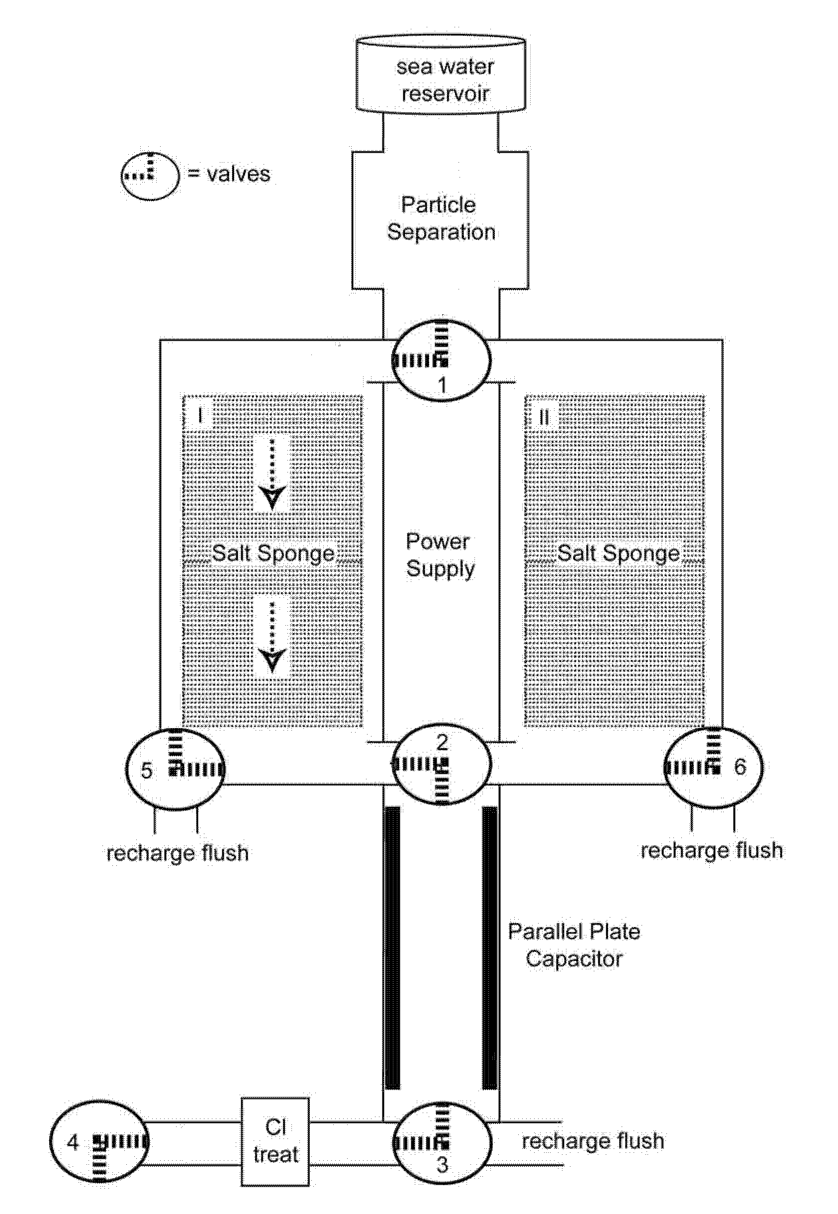
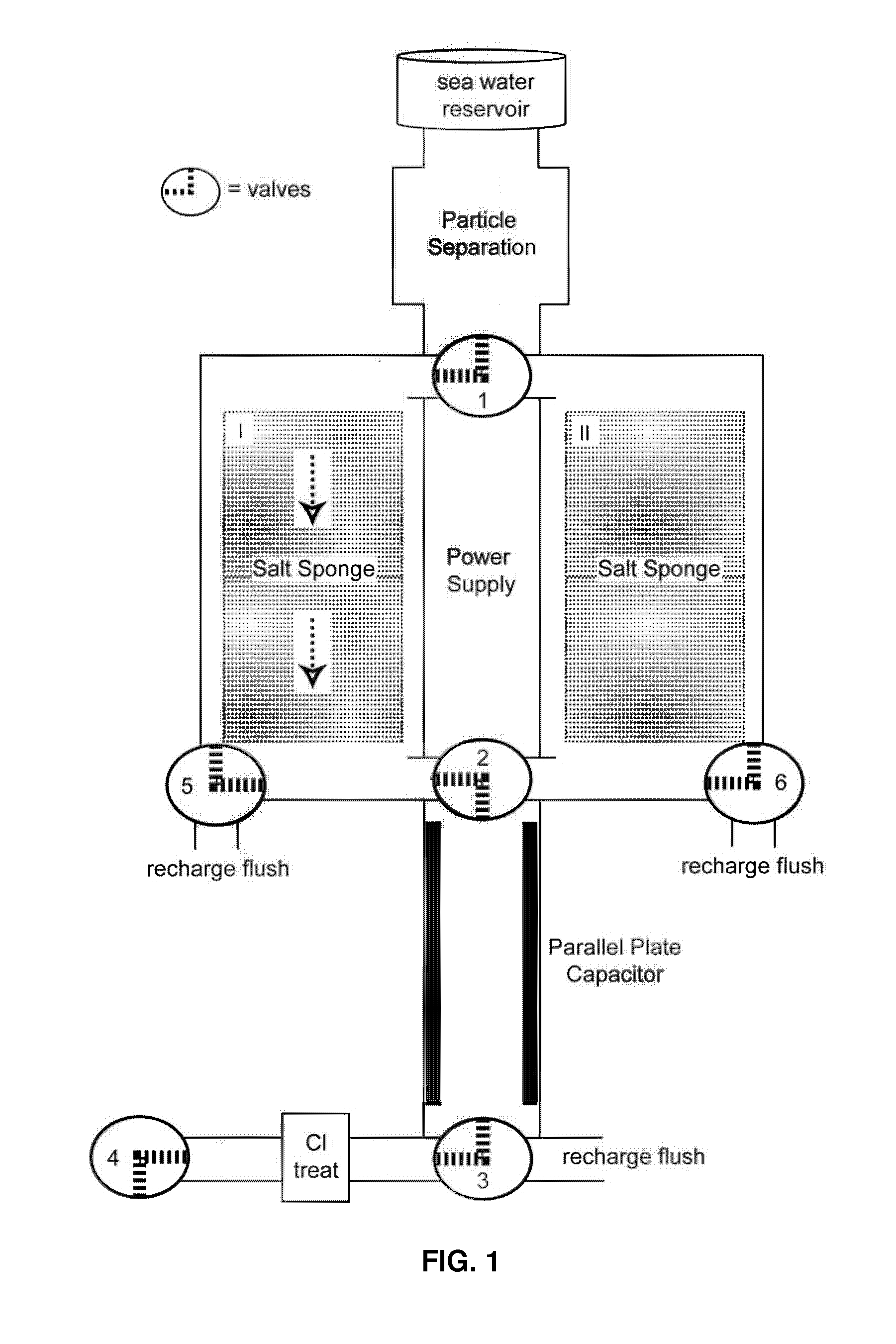
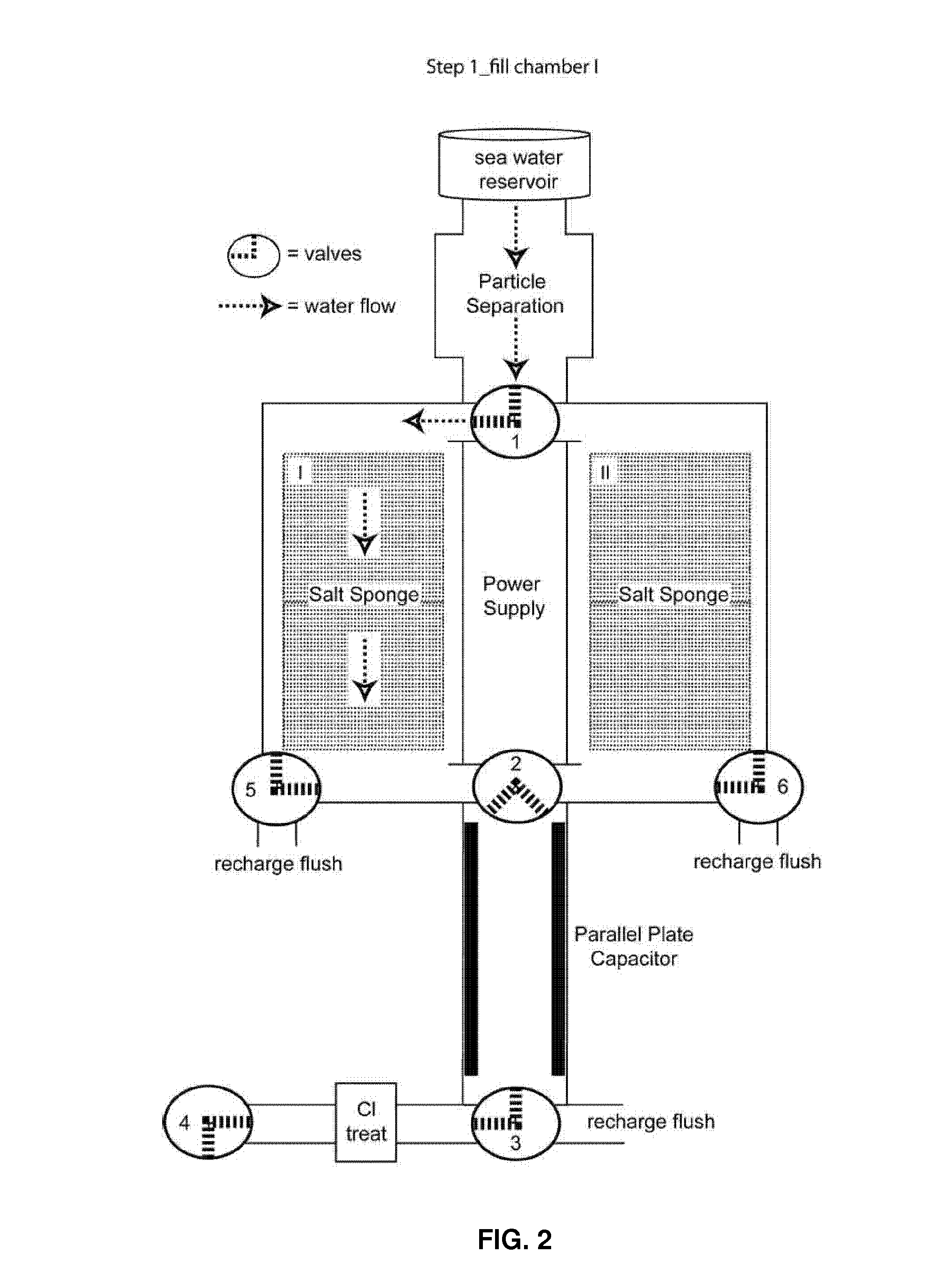
[0006]A desalination apparatus according to the invention comprises a salt sponge unit for removing a majority of salt from water. The salt sponge comprises a nanoporous, high surface area carbon scaffold to which crown ether type moieties are attached. The salt sponge in this embodiment is single use. In a preferred embodiment the salt sponge unit comprises two separate salt sponges and can comprise a valve for directing water to one or the other of the two salt sponges allowing for continuous processing. The apparatus also can additionally comprise a power supply connected to the salt sponges for applying a bias voltage to the salt sponges in order to regenerate the salt sponge material allowing for continuous reuse. The apparatus additionally may comprise a parallel plate capacitor connected after the salt sponge to remove remaining salt ions, and a chlorine treatment unit. Addition of a chlorine treatment unit, and a parallel plate capacitor or reverse osmosis system, provides a complete water purification system.

Problems solved by technology

However, these systems become more inefficient as the salt content of the water increases and are very energy intensive at deep seawater salt concentrations, e.g., 35,000 ppm.
Distillation is characterized by high energy demand, while RO systems require both high pressure produced by required pumps, and extensive maintenance due to fouling and damage of the membrane.
Thus, both distillation and RO are unsuitable for use in places in which energy is limited, such as third world countries, and for use in rapid military deployment operations.

Method used


Image

  • Water desalination apparatus and method
  • Water desalination apparatus and method
  • Water desalination apparatus and method

Examples


example

[0048]Aza-15-crown-5 ether was attached to three different carbon substrates:

(i) Plain graphite plates, which allowed for straightforward and fast testing;

(ii) Graphite fibers mesh (530 Plain Weave Carbon Fiber Fabric, Fiberglast Co.), which offered the advantage of greater surface area than graphite plates; prior to chemical modification, the material was baked in air, for removing the epoxy sizing; and

(iii) Carbon aerofoam with very large surface area with very large surface area, without coating, ridged and open cell for rapid flow through; this material enables for confining to its surface a large number of crown ether groups that retain the alkali ions from seawater.

[0049]Modification of the graphite substrates included two main steps:

(i) tethering to the surface of a linker with an outermost functional group, and

(ii) connecting the aza-15-crown 5 ether to the linker.

[0050]First, graphite substrate samples (foam or plate) were tied with 6-8″ twisted strands of Teflon tape. This...


PUM

PropertyMeasurementUnit
pressureaaaaaaaaaa
bias voltageaaaaaaaaaa

Abstract

A desalination apparatus is disclosed which uses a salt sponge unit to remove a majority of salt from water. A parallel plate capacitor can be connected after the salt sponge to remove remaining salt ions. The salt sponge is a nanoporous, high surface area carbon scaffold to which crown ethers are attached. A power supply is connected to the salt sponges for applying a bias voltage to regenerate the salt sponges. A chlorine treatment unit can be connected after the parallel plate capacitor. A method of purifying sea water using the apparatus also is disclosed.

Description

BACKGROUND OF THE INVENTION[0001]A. Field of the Invention[0002]The invention relates generally to an apparatus and method for purifying water, and more particularly an apparatus and method for water desalination (salt removal).[0003]B. Description of the Related Art[0004]Current reverse osmosis (RO) systems for large scale water purification are very efficient for meeting water quality purity on brackish salinity levels, ˜7000 ppm. However, these systems become more inefficient as the salt content of the water increases and are very energy intensive at deep seawater salt concentrations, e.g., 35,000 ppm. Distillation is characterized by high energy demand, while RO systems require both high pressure produced by required pumps, and extensive maintenance due to fouling and damage of the membrane. Thus, both distillation and RO are unsuitable for use in places in which energy is limited, such as third world countries, and for use in rapid military deployment operations.[0005]The prese...

Claims


Application Information

Patent Timeline
Patent Type & Authority Applications(United States)
IPC IPC(8): C02F9/08C02F1/00
CPCC02F1/283C02F1/285C02F1/288C02F1/441C02F1/4691C02F2303/16C02F1/76C02F2001/46119C02F2103/08C02F2201/4613C02F1/683Y02A20/131
Inventor KIPPENY, TADD C.BADORREK, CHRISTOPHER S.SENGUPTA, LOUISE C.
Owner BAE SYST INFORMATION & ELECTRONICS SYST INTERGRATION INC
Why Eureka
Eureka Blog
Learn More