Flameless cooking appliance

Active Publication Date: 2011-07-07
PRECISION COMBUSTION
View PDF26 Cites 19 Cited by
  • Summary
  • Abstract
  • Description
  • Claims
  • Application Information

AI Technical Summary

Benefits of technology

[0041]The flameless cooking apparatus of this invention incorporates several novel and advantageous features. First, the cooking apparatus of this invention employs a combustion catalyst, preferably having high surface area per unit volume, which catalyst is also resistant to degradation by vibrations, thermal stresses, and stresses due to transportation and handling. Since the combustion catalyst is placed in thermal conductive contact with the heat conductive surface, for example, the cooking surface, heat flux via conduction is rapid and more efficient as compared with heat flux via gas convection or infrared radiation as known in prior art cooking appliances. Improved heat efficiency correlates with an improved heating rate per unit weight of apparatus, as well as a more rapid startup and transi

Problems solved by technology

), which makes JP-8 among the most difficult fuels to vaporize.
Moreover, JP-8 tends to soot and therefore is one of the most difficult fuels with which to achieve clean combustion.
The aforementioned cooking apparatuses disclosed by Ryan, Babington, and Shukla require a flame burner, which results in inefficient heat transfer, excess consumption of fuel and oxidan

Method used


Image

  • Flameless cooking appliance
  • Flameless cooking appliance
  • Flameless cooking appliance

Examples


example 1

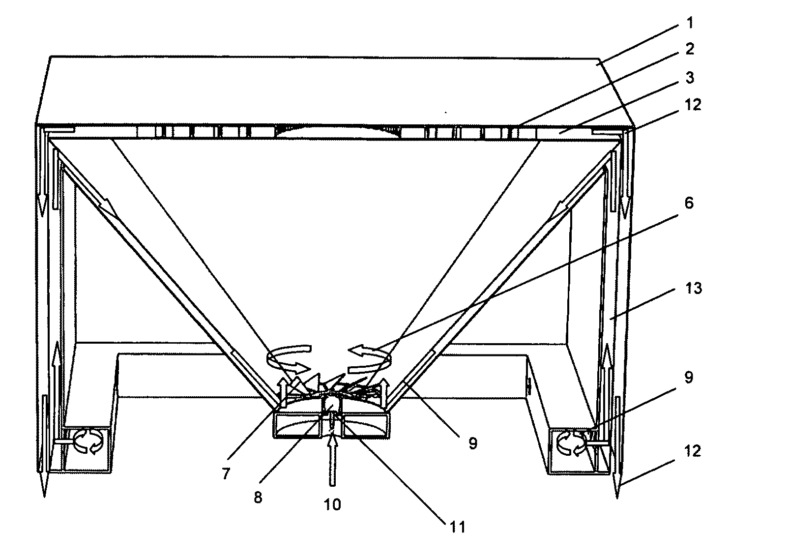
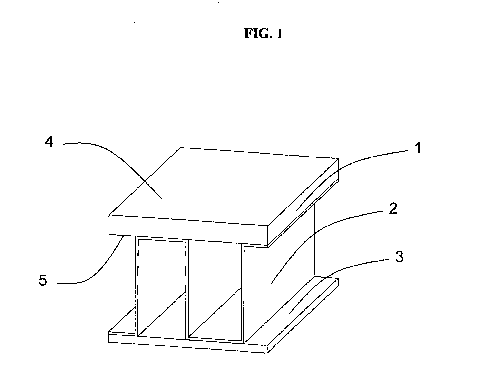
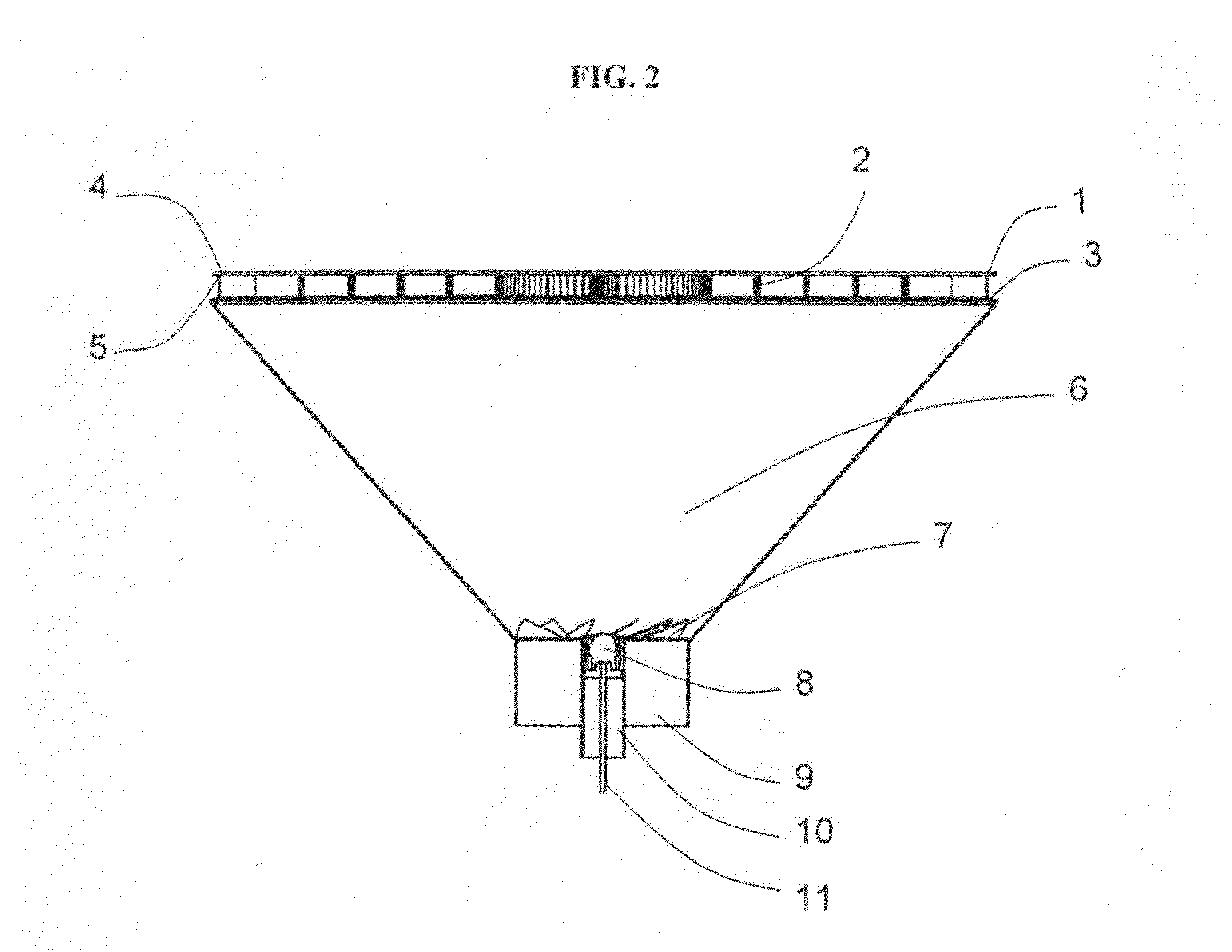
[0078]A cooking griddle (18″×18″; 2.25 ft2) (45.7 cm×45.7 cm; 2,088 cm2) in accordance with this invention was constructed in the manner shown in FIG. 2. The housing was constructed of aluminum. The cooking surface consisted of a 0.075 inch (1.88 mm) thick stainless steel sheet chosen for ease of fabrication and heat resistance. A heat spreader was constructed from 0.003 inch (0.075 mm) thick Grade 304 stainless steel sheet. The sheet was bent into a plurality of corrugated fins (1 inch long by ½ inch high, 10 fins / inch) (2.50 cm long by 1.25 cm high, 4 fins per cm), as shown in FIG. 1 (2) and FIG. 3. A series of resistance welds was made onto the ridge of each fin (top side contacting underside of cooking surface FIG. 1(5)) by means of the copper electrode method described in detail hereinabove. A Microlith® brand combustion catalyst obtained from Precision Combustion, Inc. of North Haven, Conn., and comprising noble metal deposited on ultra-short-channel-length metal mesh substrat...


PUM


Abstract

A flameless cooking apparatus for use with liquid fuels and for indoor or outdoor use under field operations. The burner exhibits low CO and hydrocarbon emissions and meets standards for burner thermal efficiency when used with JP-8 fuel. The apparatus employs a catalytic burner having among its parts (i) a combustion catalyst; (ii) a conductive surface, e.g., cooking surface; and (iii) in between the catalyst and the conductive surface and in direct physical contact with both surfaces, a heat spreader for conductively transferring heat of combustion from the catalyst to the conductive surface. Also claimed are a method of heat flux and a method of cooking.

Description

[0001]This invention was made with support from the U.S. government under U.S. Contract No. W911QY-09-C-0028. The U.S. Government holds certain rights in this invention.FIELD OF THE INVENTION[0002]This invention pertains to a flameless combustion apparatus for use in heat transfer processes, such as, cooking processes. More specifically, this invention pertains to a flameless cooking appliance designed to be portable for use in outdoor and indoor field operations, and preferably, designed for a liquid fuel.BACKGROUND OF THE INVENTION[0003]Portable cooking devices are well known in the art. Such devices find utility in “backyard” barbecues, in camping and recreational environments, and in preparing meals for military personnel on field operations, displaced persons in refugee camps, and victims of storms. A modern-day field burner should be capable of utilizing a variety of fuels, including gasoline, kerosene, ethanol, methanol, diesel, and aircraft jet fuels, such as JP-4, JP-5, JP-...

Claims


Application Information

Patent Timeline
IPC IPC(8): F24C3/10F23Q11/04F23N1/02F24C15/32A23L1/01A23L5/10
CPCF23C13/00F23C13/08F23D11/40Y02B40/166F23D2212/20F23D2214/00F24C3/067F23D14/18Y02B40/00Y02E20/34
Inventor ROYCHOUDHURY, SUBIRMASTANDUNO, RICHARD T.CROWDER, BRUCEBAIRD, BENJAMIN D.
Owner PRECISION COMBUSTION
Why Eureka
Try Eureka