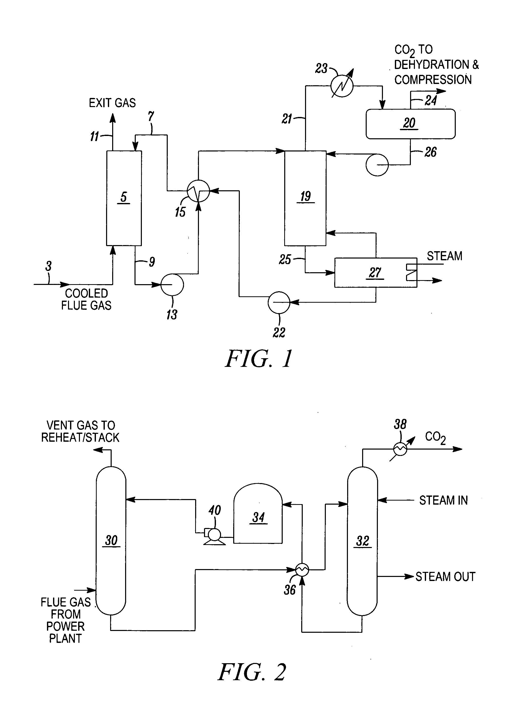
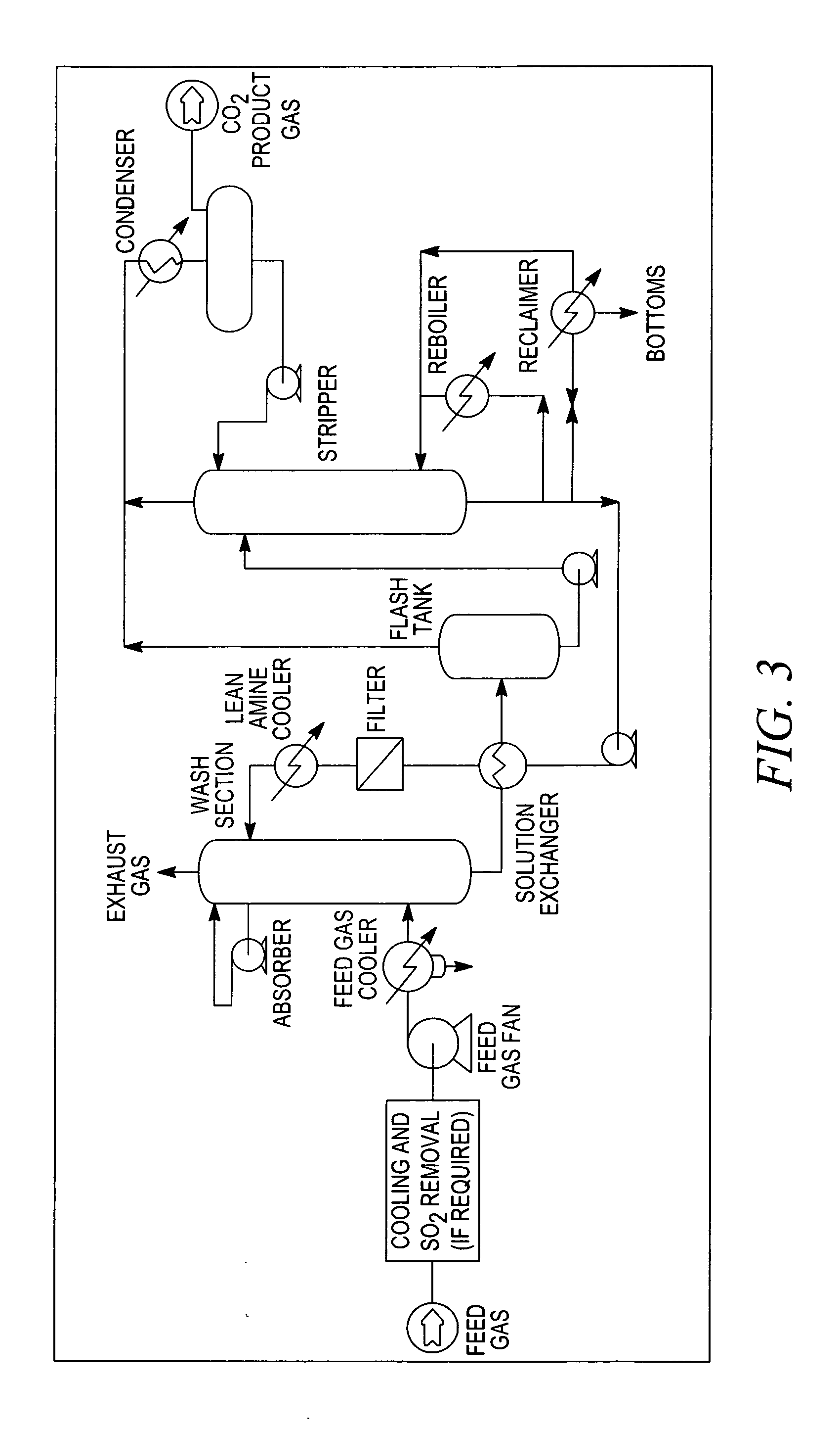
[0045]The present invention preferably relates to a method and apparatus for capturing the
flue gas of a
coal fired power
plant, incinerator or chemical
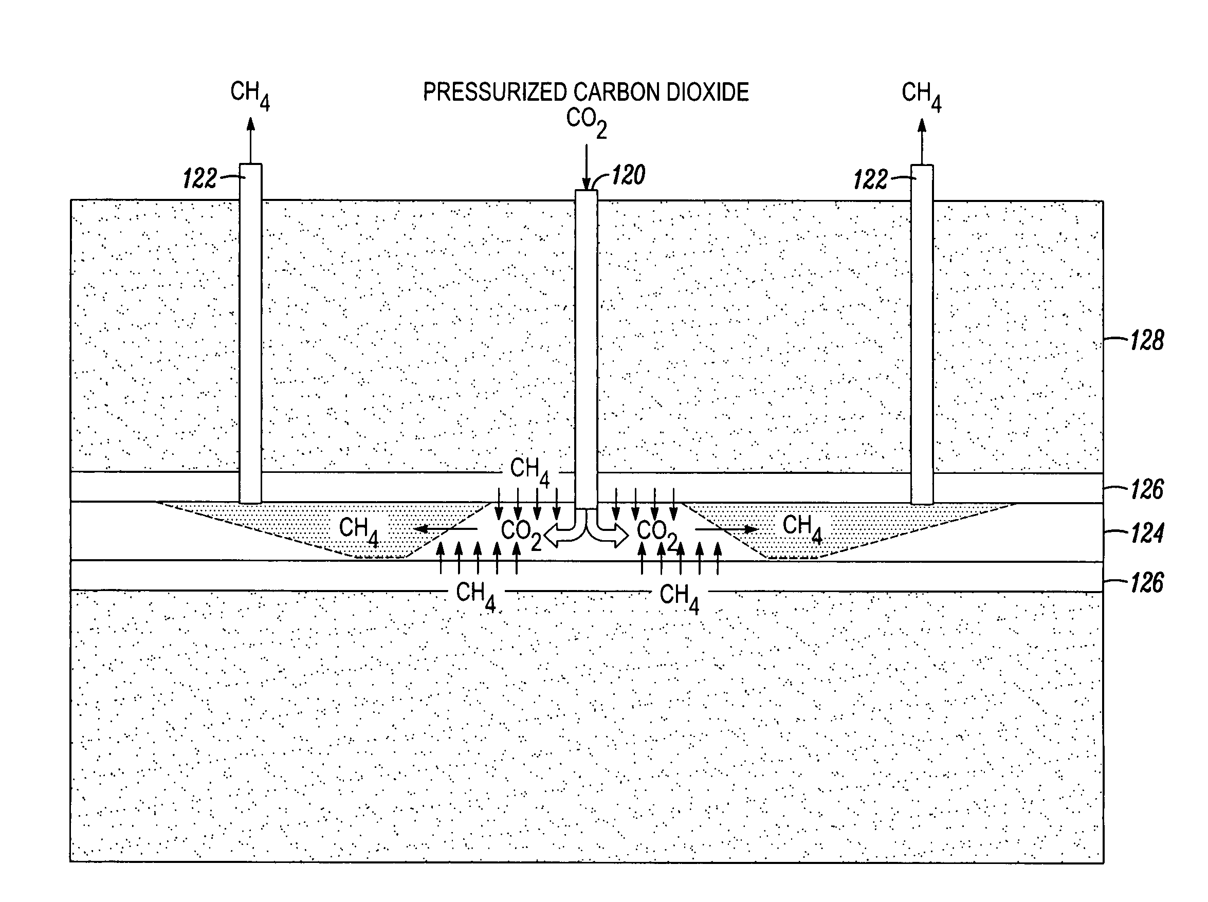
processing plant, and separating the CO2 gas therefrom, and converting the CO2 gas captured from the power plant into a cold pressurized liquid CO2, and injecting it under pressure into an underground startum or layer of coal and / or gas shale, and in particular, releasing the pressurized liquid CO2 through perforations, and using it to create narrow elongated fractures and openings within the
layers, to increase their permeability, thereby increasing the flow of natural gas found in the pores and joints therein, as well as increasing the adsorbtion of CO2 and simultaneous desorbtion of CH4, such that the natural gases normally found within the formations can be released, recovered and sold to offset the overall cost of capturing and sequestering the CO2.
[0051]Once the LCO2 has been pressurized and chilled, it is ready to be injected into the pipes and released into the strata. However, to avoid premature warming of the liquid CO2, it is desirable to inject
liquid nitrogen into the
pipe first, which helps to pre-chill the
pipe, so that when the LCO2 is injected, it will not change phase to a gas prematurely. Nevertheless, it is not expected that the
pipe will stay at the same temperature, and therefore, a
thermocouple is preferably provided to measure the temperature of the pipe and thus the extent to which the pipe is pre-chilled can be controlled.
[0053]By forcing the
high pressure liquid CO2 into the stratum via a pre-chilled vertical pipe with an end extension of perforations, the
high pressure LCO2 is vented through the perforations to fracture a long cavity of small
diameter (pencil-like) openings in all radial directions extending from the perforated pipe. The
high pressure liquid CO2 is forced through each perforated hole and penetrates the shale or coal stratum, wherein, when the pressure exceeds the fracture gradient of the rock formation, fractures are created in the rock. Not only does this help release the natural gas trapped within the formation's pores and joints, but the broken fragments can then be made more susceptible to adsorption of LCO2 and GCO2, and
desorption of CH4, which allows more coal or shale fragments to be exposed to CO2, such that more adsorption can take place, which means that more CO2 can then be sequestered, which also means that more natural gas can be released and recovered from the site.
[0054]The newly created surfaces within the
drill hole and radiating cracks can cause the LCO2 to warm up. Likewise, pressurizing the LCO2 can increase the temperature thereof, and when the cryogenic pump is
shut down, the
liquid pressure can decrease. For example, when pressure decreases to 400 psi, and the temperature increases to plus 40° F. (or any other point on the curve), the liquid LCO2 can suddenly change phase explosively, wherein the expansion of the gaseous CO2 can extend the reach of the cracks and create more exposed surface area within the stratum. This process of rubblization exposes the material in the product zone further by forming a multitude of smaller particles and a huge sum of exposed surfaces for the capture of CO2 and release of CH4.
[0055]While it is preferable that this
phase change occur after the pump is turned off, there is a possibility that the
phase change could occur before the pipes are sealed. This can depend on the depth of the formation, wherein, at greater depths, the pressure is greater, and therefore, the
phase change will be less likely to occur prematurely, whereas, at shallower depths, the pressure will be less, and therefore, the phase change is more likely to occur as the LCO2 is exposed to its warmer surroundings. But regardless of when it takes place, this sudden phase change occurs explosively and radiates fractures in all directions, thereby increasing the volumes of fractures for further adsorption of CO2 and
desorption of CH4.
[0057]With all vents closed, the pressurization of the formation is allowed to continue, and thus, further fracturing can occur, in which case, CH4 can continue to be desorbed, and CO2 can continue to be adsorbed, into the surfaces made free by the
desorption of CH4. This containment is preferably sustained for a
residence period of time to permit the LGCO2 and GCO2 to be completely adsorbed and the lower density natural gas to migrate into the perforated vertical collection pipes and flow upward to be recovered. The pressure is preferably sustained to reduce the required
residence time.

