Method of manufacturing a vertical-type semiconductor device and method of operating a vertical-type semiconductor device

a vertical-type semiconductor and semiconductor technology, applied in semiconductor devices, digital storage, instruments, etc., can solve the problems of difficult control of mos transistors by gates, leakage current properties and threshold voltages in vertical-type pillar transistors formed in each of the semiconductor patterns, and difficult to ensure electrical properties of vertical-type pillar transistors. , to achieve the effect of high performan

Active Publication Date: 2011-09-01
SAMSUNG ELECTRONICS CO LTD
View PDF4 Cites 17 Cited by
  • Summary
  • Abstract
  • Description
  • Claims
  • Application Information

AI Technical Summary

Benefits of technology

[0010]Example embodiments provide a semiconductor device including a vertical-type pillar transistor with high performance.
[0043]The vertical-type semiconductor device according to the embodiments of the inventive concept has excellent performances. Data may be stored in the pillar-shaped single-crystalline semiconductor pattern without any defect. Accordingly, the vertical-type semiconductor device may input and output data without additional data storage structure, to thereby improve degrees of integration of the device. Further, since the mask pattern is not provided on the upper surface of the single-crystalline semiconductor pattern, the second impurity region may be easily formed to thereby reduce failures of processes. Accordingly, it is easy to manufacture a memory device of an array structure including the vertical-type pillar transistors, according to the embodiments of the inventive concept.

Problems solved by technology

Accordingly, it becomes difficult to control the MOS transistor by a gate.
That is, when the semiconductor pattern has any crystal defect, leakage current properties and threshold voltages in the vertical-type pillar transistor formed in each of the semiconductor patterns may not be uniform.
However, because it is considerably more difficult than the bulk substrate to form the semiconductor pattern without any crystal defect, it may be not easy to ensure electrical properties of the vertical-type pillar transistors.
Additionally, processes of forming a gate and a source / drain in the pillar-shaped semiconductor pattern are considerably more complicated than those in the substrate.
Further, when the vertical-type pillar transistors are formed to have an array structure, more complicated processes need to be additionally performed, such that the incidence of process failures increases.
Accordingly, it may be difficult to manufacture a memory device of an array structure including the vertical-type pillar transistors.

Method used


Image

  • Method of manufacturing a vertical-type semiconductor device and method of operating a vertical-type semiconductor device
  • Method of manufacturing a vertical-type semiconductor device and method of operating a vertical-type semiconductor device
  • Method of manufacturing a vertical-type semiconductor device and method of operating a vertical-type semiconductor device

Examples


embodiment 1

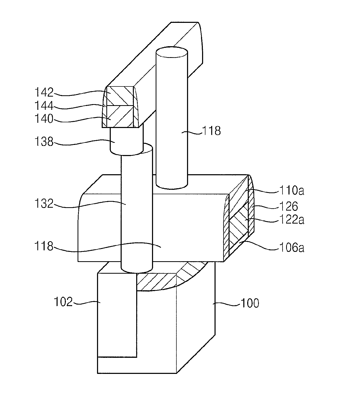
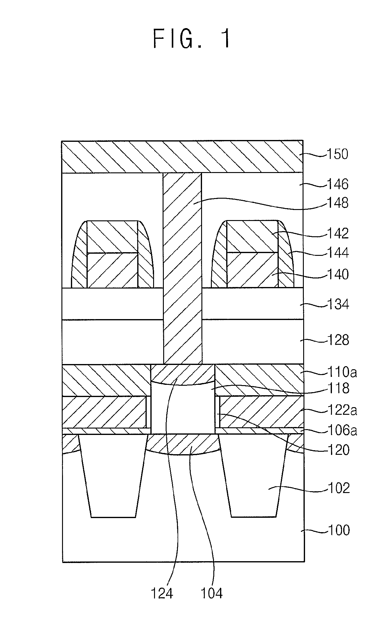
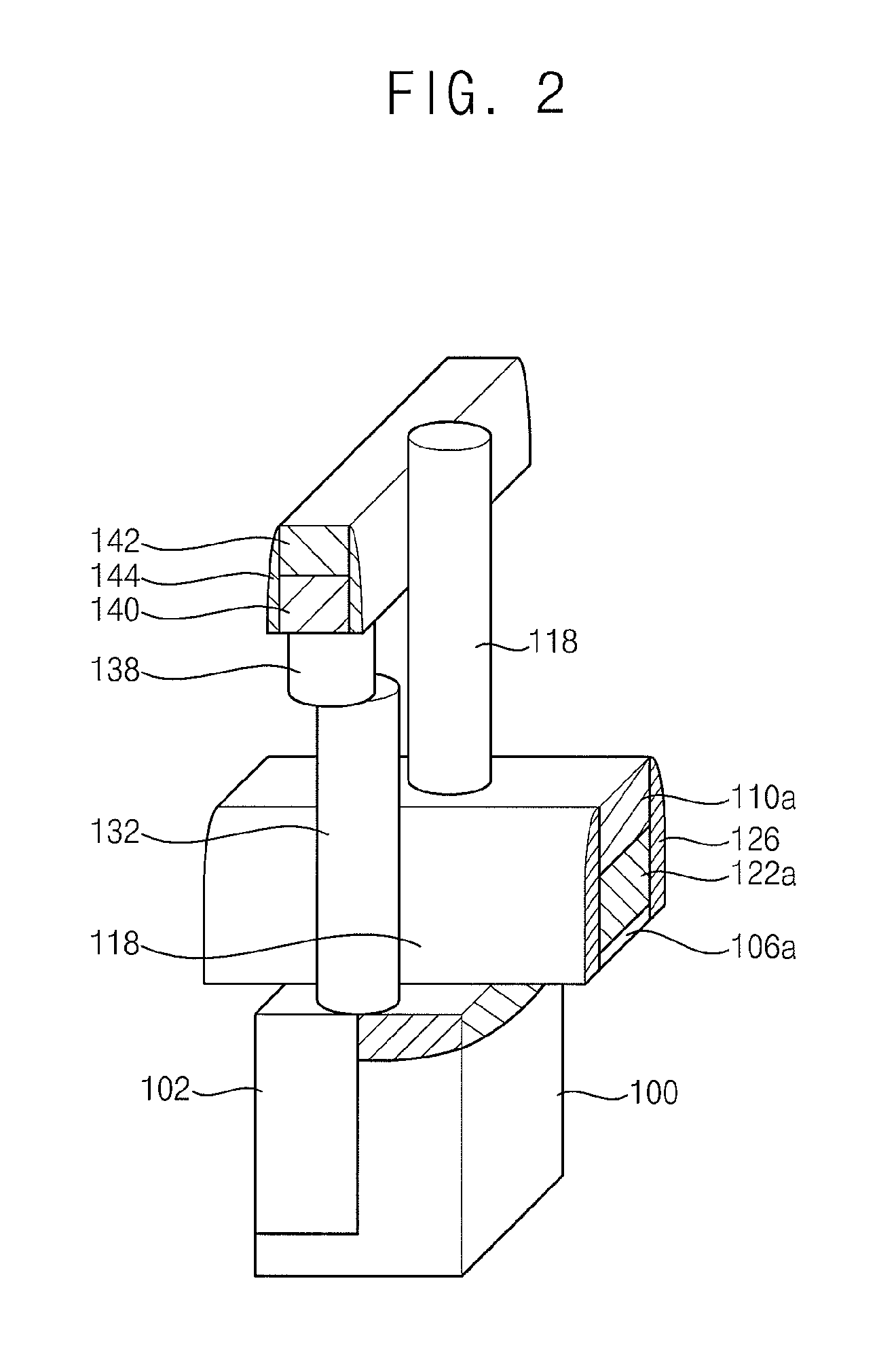
[0062]FIG. 1 is a cross-sectional view illustrating a DRAM device including a vertical-type pillar transistor in accordance with a first example embodiment. FIG. 2 is a perspective view illustrating the DRAM device in FIG. 1.

[0063]Referring to FIG. 1, a substrate 100 having an active region and an isolation region is prepared. The substrate 100 may include single-crystalline semiconductor material. For example, the substrate 100 may include single-crystalline silicon. Trenches are formed in the isolation region of the substrate 100. An isolation layer pattern 102 is formed in the trench.

[0064]The active region and the isolation region extend in a first direction. The active region and the isolation region having linear shapes are arranged alternately with one another.

[0065]A single-crystalline semiconductor pattern 118 having a pillar shape is provided on the active region of the substrate 100. The single-crystalline semiconductor pattern 118 may includes single-crystalline silicon....

embodiment 2

[0159]FIG. 28 is a cross-section view illustrating a DRAM device including a vertical-type pillar transistor in accordance with a second example embodiment.

[0160]A vertical-type pillar transistor, a bit line and a contact plug of a DRAM device according to the present embodiment are substantially the same as in Embodiment 1. However, unlike the DRAM device in Embodiment 1, a capacitor 208 is provided on an upper surface of the contact plug in Embodiment 2.

[0161]The capacitor 208 includes a lower electrode 202, a dielectric layer 204 and an upper electrode 206. The lower electrode 202 and the upper electrode 206 may include metal. Alternatively, the lower electrode 202 and the upper electrode 206 may include polysilicon.

[0162]As illustrated in the figure, the lower electrode 202 may have a cylindrical shape. In this case, a contact area between the dielectric layer 204 and the lower electrode 202 may be increased to provide a higher capacitance.

[0163]Although it is not illustrated in...

embodiment 3

[0176]FIG. 29 is a cross-section view illustrating a memory device including a vertical-type pillar transistor in accordance with a third example embodiment.

[0177]A vertical-type pillar transistor, a bit line and a contact plug of a memory device according to the present embodiment are substantially the same as in Embodiment 1. However, unlike the DRAM device in Embodiment 1, a phase changeable structure 254 is provided on an upper surface of the contact plug.

[0178]The phase changeable structure 254 has a staked structure of a phase changeable layer pattern 250 and an upper electrode 252. For example, the upper electrode 252 may include metal. For example, the upper electrode 252 may include tungsten, titanium, titanium nitride, tantalum, tantalum nitride, molybdenum nitride, niobium nitride, titanium silicon nitride, aluminum, titanium aluminum nitride, titanium boron nitride, zirconium aluminum nitride, molybdenum silicon nitride, tungsten boron nitride, zirconium aluminum nitride...


PUM

PropertyMeasurementUnit
temperatureaaaaaaaaaa
semiconductoraaaaaaaaaa
lengthaaaaaaaaaa

Abstract

In a vertical-type semiconductor device, a method of manufacturing the same and a method of operating the same, the vertical-type semiconductor device includes a single-crystalline semiconductor pattern having a pillar shape provided on a substrate, a gate surrounding sidewalls of the single-crystalline semiconductor pattern and having an upper surface lower than an upper surface of the single-crystalline semiconductor pattern, a mask pattern formed on the upper surface of the gate, the mask pattern having an upper surface coplanar with the upper surface of the single-crystalline semiconductor pattern, a first impurity region in the substrate under the single-crystalline semiconductor pattern, and a second impurity region under the upper surface of the single-crystalline semiconductor pattern. The vertical-type pillar transistor formed in the single-crystalline semiconductor pattern may provide excellent electrical properties. The mask pattern is not provided on the upper surface of the single-crystalline semiconductor pattern in the second impurity region, to thereby reduce failures of processes.

Description

RELATED APPLICATIONS[0001]This application is a continuation application of U.S. patent application Ser. No. 12 / 478,081, filed on Jun. 4, 2009, which claims the benefit of Korean patent application number 10-2008-0052368, filed on Jun. 4, 2008, in the Korean Intellectual Property Office, the contents of which applications are incorporated herein in their entirety by reference.BACKGROUND[0002]1. Field[0003]Example embodiments relate to a vertical-type semiconductor device, a method of manufacturing the vertical-type semiconductor device and a method of operating the vertical-type semiconductor device. More particularly, example embodiments relate to a semiconductor device having a vertical-type pillar transistor suitable for a cell array structure, a method of manufacturing the semiconductor device and a method of operating the semiconductor device.[0004]2. Description of the Related Art[0005]Generally, as semiconductor devices become highly integrated, dimensions of active regions a...

Claims


Application Information

Patent Timeline
Patent Type & Authority Applications(United States)
IPC IPC(8): G11C7/00H01L21/336H01L21/8242
CPCH01L27/108H01L27/10802H01L29/7841H01L29/66666H01L29/7827H01L27/10876H10B12/20H10B12/00H10B12/053H10B12/395
Inventor SON, YONG-HOONLEE, JONG-WOOKKANG, JONG-HYUK
Owner SAMSUNG ELECTRONICS CO LTD
Why Eureka
Try Eureka