Method and apparatus for locking a laser with a resonant cavity

a laser and cavity technology, applied in the field of ultrasensitive analysis of gaseous species, can solve the problems of low immunity, inability to find a single commercial gas detection product, and limited impact on the gas sensing industry, and achieve the effects of improving the sensitivity of the laser, improving the sensitivity, and low cos

Active Publication Date: 2011-09-08
LI COR
View PDF40 Cites 59 Cited by
  • Summary
  • Abstract
  • Description
  • Claims
  • Application Information

AI Technical Summary

Benefits of technology

[0020]The present invention describes a method and apparatus for the photo-acoustic identification and quantification of one or more analyte species in a gaseous or liquid medium based upon enhancement of a low power laser radiation by locking it to an optical power buildup cavity. The method is suitably called OPBC-PAS. The invention offers a number of particular configurations of OPBC-PAS gas sensors that are especially advantageous for building compact low cost automatic sensors with high sensitivity and which are capable of long-term (e.g., years) unattended operation.

Problems solved by technology

PAS has been among the methods of ultra-sensitive spectroscopy popular in scientific research, but to date it has had a very limited impact on the gas sensing industry.
Hz. However, the sensitive general purpose microphones used in PAS required elaborate acoustic isolation of the sample cells, and low immunity to ambient noise may be a reason impeding its use in noisy industrial environm
ensor size. Surprisingly however, even in 2009, seven years after the invention of QEPAS, one cannot find a single commercial gas detection product based
The explanation is simple—the power of the commercially available laser sources is too low, and therefore the limits of detection on concentration are non-competitive with other methods.
06)]. One can say that these acoustic resonance enhancement techniques have been generally optimized and that one cannot reasonably expect a further responsivity increase of no greater than several tens of per
d in QEPAS. This means that the detection threshold of both sensors cannot be further improved, and the only way to lower the NEA is to increase the excit
ation power. With semiconductor lasers operating in the C- or L-band telecommunication range the power can be increased to watts level by using an Erbium-doped fiber amplifier, [see M. Webber, et. al., Appl. Opt., 42 (12), 2119-2126 (2003)] but this solution has an unacceptab
ly high price. Another way to increase the excitation beam power by placing the photo-acoustic cell inside the resonant cavity of a laser is obviously not applicable to DFB semiconductor lasers, and it would not be practical even with an external cavity diode laser because the power buildup is rather small in the lossy cavities
irrors reflectivity. However, this work cannot be considered as showing encouraging prospects for building industrial gas OPBC-PAS sensors
ith no OPBC enhancement. A second important reason is that the method of locking the diode laser radiation to the cavity described in the Rossi paper was only marginally effective even in a perturbation-free
laboratory environment. The unstable and unreliable operation of the diode to cavity lock also resulted in very poor stability of the buildup intensity dependence as a function of time as one can see from FIG.
An unavoidable drawback of such approach is that the locking cannot be done during periods when the laser is off.
After the laser is turned on again, a large error signal results in over-reaction of the locking system, and the lock can be lost again because of this over-reaction.
As a result such systems have low immunity to external perturbations, high instability of the buildup power, and are essentially useless for applications in field useable systems.

Method used


Image

  • Method and apparatus for locking a laser with a resonant cavity
  • Method and apparatus for locking a laser with a resonant cavity
  • Method and apparatus for locking a laser with a resonant cavity

Examples


Embodiment Construction

[0044]We now provide a detailed description of the method of the invention and several embodiments of the apparatus applicable to the method.

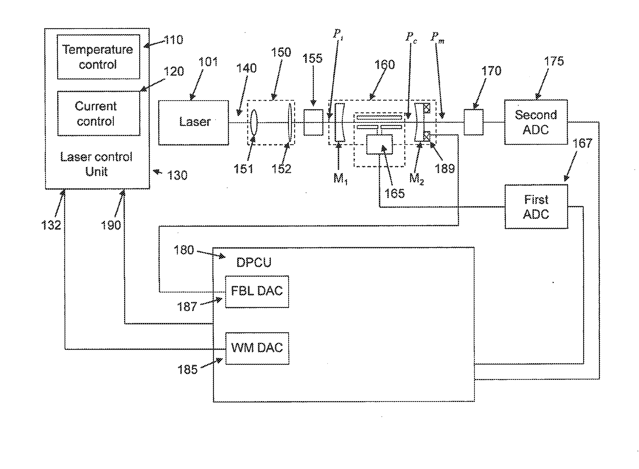
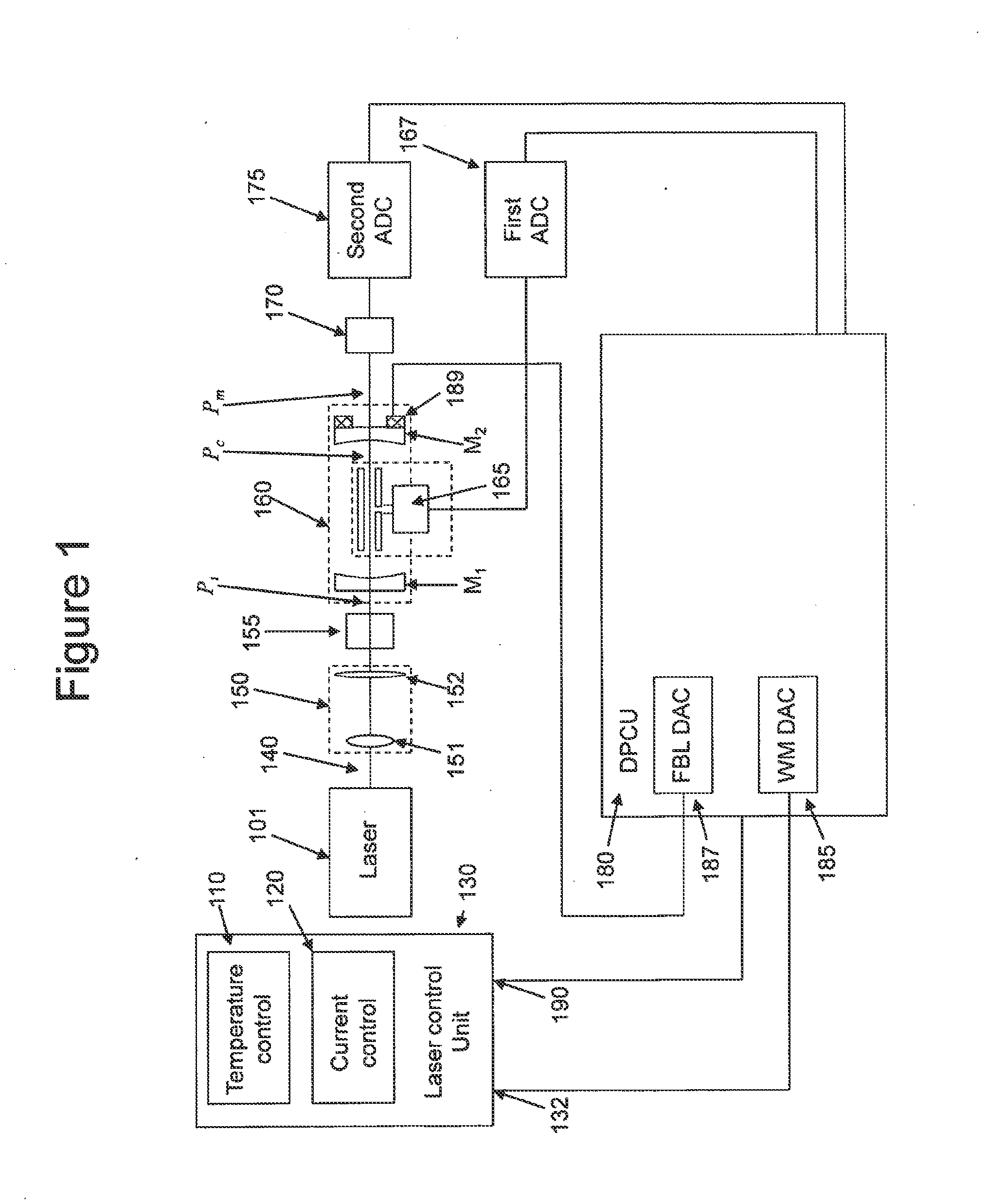
[0045]A schematic diagram of the gas detection system of the present invention is shown in FIG. 1. The present invention in a preferred embodiment contains a semiconductor laser source 101, preferably a distributed feedback (DFB) laser emitting a single emission line that can be tuned in the vicinity of the absorption line of the analyte species of interest within a range of several wave numbers. The operating wavelength of the laser can be changed or modulated, for example, by changing the operating temperature of the semiconductor laser chip, and / or its drive current. This is accomplished by electronic modules known in the art such as a diode laser temperature controller 110 and / or a low noise diode laser current controller 120. In other embodiments the laser can be of other known type subject to the requirement that its wavelength of operati...


PUM

PropertyMeasurementUnit
absorption coefficientaaaaaaaaaa
volumeaaaaaaaaaa
volumeaaaaaaaaaa

Abstract

A method and apparatus for the photo-acoustic identification and quantification of one or more analyte species present in a gaseous or liquid medium in low concentration utilizing a laser and a resonant optical cavity containing the medium and having within the cavity at least two partially transparent mirrors, one of which is a cavity coupling mirror and one of which is moveably mounted on an assembly responsive to an input signal.

Description

CROSS-REFERENCES TO RELATED APPLICATIONS[0001]The present application is a continuation of U.S. patent application Ser. No. 12 / 660,614, filed Mar. 2, 2010 (Attorney Docket No. 020031-013500US), which is hereby incorporated by reference in its entirety for all purposes.STATEMENT AS TO RIGHTS TO INVENTIONS MADE UNDER FEDERALLY SPONSORED RESEARCH OR DEVELOPMENT[0002]NOT APPLICABLEREFERENCE TO A “SEQUENCE LISTING,” A TABLE, OR A COMPUTER PROGRAM LISTING APPENDIX SUBMITTED ON A COMPACT DISK[0003]NOT APPLICABLEBACKGROUND OF THE INVENTION[0004]This invention belongs to the field of ultra-sensitive analysis of gaseous species or more specifically, to spectroscopic methods of analysis such as, for example, Photo Acoustic Spectroscopy (PAS) that benefit from a high intensity light source. PAS has been among the methods of ultra-sensitive spectroscopy popular in scientific research, but to date it has had a very limited impact on the gas sensing industry. Many years of PAS research as an analy...

Claims


Application Information

Patent Timeline
Patent Type & Authority Applications(United States)
IPC IPC(8): G01J1/00G01J1/42G02F1/35
CPCG01N21/1702G01N21/39G01N2021/1704H01S5/005H01S5/0064H01S5/0656G01N2021/1708
Inventor KACHANOV, ALEXANDERKOULIKOV, SERGUEI
Owner LI COR
Why Eureka
Try Eureka