Detecting apparatus and imaging apparatus

Inactive Publication Date: 2011-10-06
CANON KK
View PDF4 Cites 6 Cited by
  • Summary
  • Abstract
  • Description
  • Claims
  • Application Information

AI Technical Summary

Benefits of technology

[0008]In a detection apparatus and an imaging apparatus according to the present invention, the intensity of the detection signal obtained by the detecting section is raised to allow observations to be made more accurately than ever because a coherent electromagnetic wave source can be employed with a relatively high output level. While theoretically an electromagnetic wave of any frequency can be used for the purpose of the present invention, the present invention is particularly remarkably advantageous for using a terahertz wave including frequencies within the frequency band between 30 GHz and 30 THz, for which it is difficult to provide a highly sensitive detector and a high power electromagnetic wave source.

Problems solved by technology

However, incoherent electromagnetic wave sources provide a lower output level and are less stable if compared with CW (continuous wave) electromagnetic wave sources to make it difficult to realize accurate measurements.
Particularly, many incoherent electromagnetic wave sources in the terahertz wave region have problems including that the incoherent electromagnetic sources can produce only weak signals of the order of microwatts and require a large apparatus.

Method used


Image

  • Detecting apparatus and imaging apparatus
  • Detecting apparatus and imaging apparatus
  • Detecting apparatus and imaging apparatus

Examples


embodiment 1

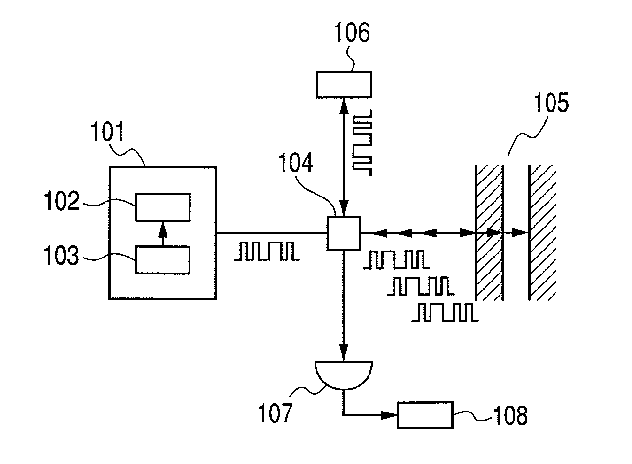
[0045]This embodiment relates to a possible configuration for realizing an imaging apparatus according to the present invention. In this embodiment, the present invention is applied to an imaging apparatus for acquiring information on a sample in the depth direction by means of a spatial optical system.

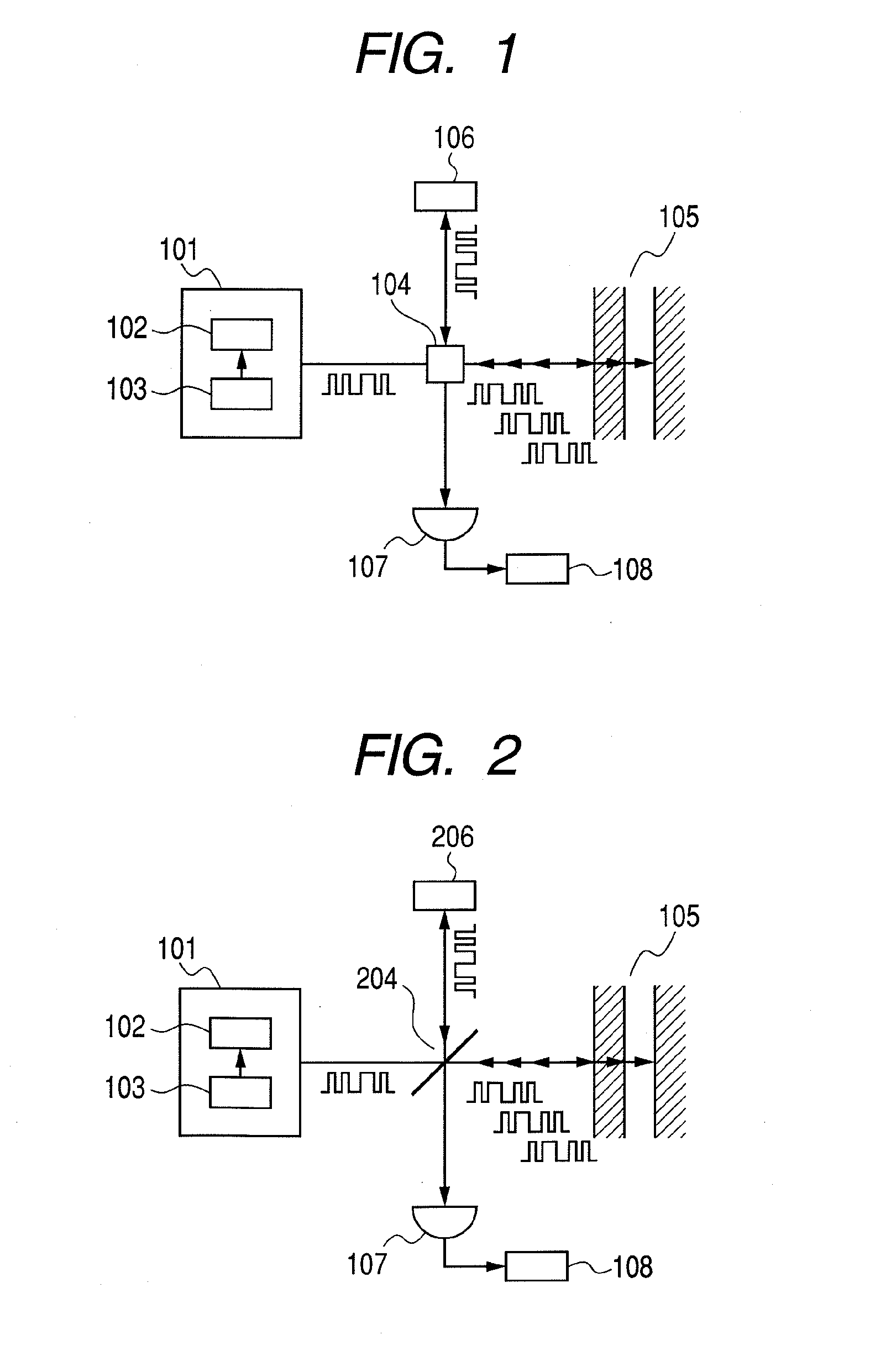
[0046]FIG. 2 is a schematic circuit diagram of the imaging apparatus of this embodiment. In this embodiment, a beam splitter 204 as shown in FIG. 2 is used as coupler section. A reflecting section 206 such as a mirror that optically reflects electromagnetic waves is used as delaying section.

[0047]A quantum cascade laser (QCL) is used for the laser source 102, although some other semiconductor device such as a resonant tunneling diode (RTD) may alternatively be used for the laser source 102. Still alternatively, an oscillator that utilizes a nonlinear optical crystal or an oscillator that utilizes an electron tube such as a backward wave oscillator (BWO) may be used for the laser sourc...

embodiment 2

[0051]This embodiment also relates to a possible configuration for realizing an imaging apparatus according to the present invention. More specifically, the imaging apparatus of this embodiment is obtained by modifying the apparatus of Embodiment 1 by using an optical waveguide for the electromagnetic wave propagation route.

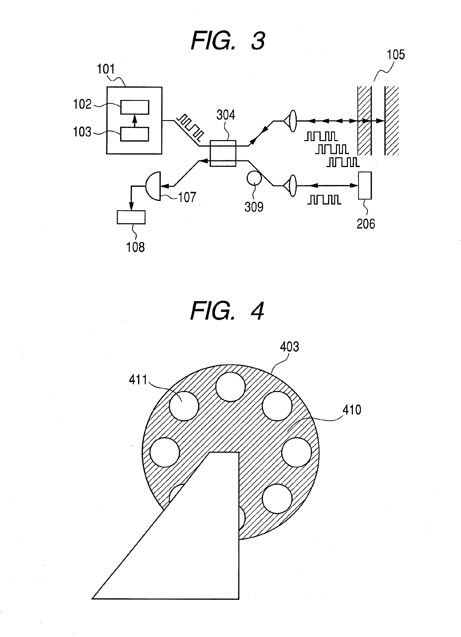
[0052]FIG. 3 is a schematic circuit diagram of the imaging apparatus of this embodiment. As shown in FIG. 3, an optical waveguide 309 of optical fiber is employed for the electromagnetic wave propagation route. A fiber coupler 304 is employed for the coupler section 104 correspondingly.

[0053]With this arrangement, the optical waveguide 309 operates as main electromagnetic wave propagation route. As a result, any possible interferences between the electromagnetic wave and external noises can be reduced to improve the S / N ratio and hence the accuracy of observation. Additionally, this arrangement of using an optical waveguide 309 of optical fiber can simplify the o...

embodiment 3

[0054]This embodiment differs from the above-described embodiments in terms of the method of generating a pseudoincoherent electromagnetic wave by means of the generating section 101. More specifically, an incoherent electromagnetic wave is produced by mechanically sequentially switching the part that transmits an electromagnetic wave and the part that reflects an electromagnetic wave according to a code pattern that changes in time series as described earlier.

[0055]For example, a rotary disk 403 as shown FIG. 4 is employed for the diffusing section 103. Referring to FIG. 4, the rotary disk 403 has reflecting sections 410 that reflect an electromagnetic wave and transmitting sections 411 that transmit an electromagnetic wave. The reflecting sections 410 are typically made of an electro-conductive metal. The transmitting sections 411 may be cavities that may or may not be filled with a substance that is maximally transparent relative to the electromagnetic wave to be transmitted thro...


PUM


Abstract

A detection apparatus and an imaging apparatus are capable of accurately conducting non-destructive observation of a target by using an incoherent electromagnetic wave. The detection apparatus has a generating section, a first coupler section, a delaying section, a second coupler section and a signal processing section. The generating section 101 includes a coherent electromagnetic wave source 102 and a diffusing section 103 for generating a pseudoincoherent electromagnetic wave by changing a propagation state of the coherent electromagnetic wave in accordance with a code pattern. The incoherent electromagnetic wave is split into first and second waves and the first wave is affected by the target of observation while the second wave is delayed by the delaying section. The first and second waves are then coupled to produce a coupled wave having a correlation signal of them and the signal is utilized to acquire information on the inside of the target of observation.

Description

[0001]TECHNICAL FIELD[0002]The present invention relates to a detection apparatus for acquiring information on a target of observation by means of an electromagnetic wave and also to an imaging apparatus for acquiring an image of a target of observation.BACKGROUND ART[0003]Non-destructive testing techniques have been developed in recent years, using high frequency electromagnetic waves including frequencies of an arbitrarily selected frequency band (to be referred to as terahertz waves hereinafter) out of from the millimeter wave to the terahertz wave region (from 30 GHz down to 30 THz). Terahertz waves are known to contain absorption lines of various different substances including those of biomolecules. Applications of the frequency range include safe imaging techniques for fluoroscopic examinations that can eliminate the use of X-rays and spectrometric techniques for looking into the bonding conditions of molecules by determining the absorption spectra and the complex permittivity...

Claims


Application Information

Patent Timeline
IPC IPC(8): G01R27/04G01N21/35G01N21/17G01N21/3581H01S3/10
CPCG01N21/4795G01N21/3581
Inventor ITSUJI, TAKEAKI
Owner CANON KK
Why Eureka
Try Eureka