Thermal interface materials with good reliability

a technology of thermal interface materials and reliability, applied in the direction of semiconductor/solid-state device details, lighting and heating apparatus, manufacturing tools, etc., can solve the problems of high thermal resistance at the interface, impairing the transfer of heat away from the semiconductor device, and generating heat from the device promptly and adequately removed, etc., to achieve good reliability

Inactive Publication Date: 2011-11-03
INDIUM CORPORATION
View PDF11 Cites 18 Cited by
  • Summary
  • Abstract
  • Description
  • Claims
  • Application Information

AI Technical Summary

Benefits of technology

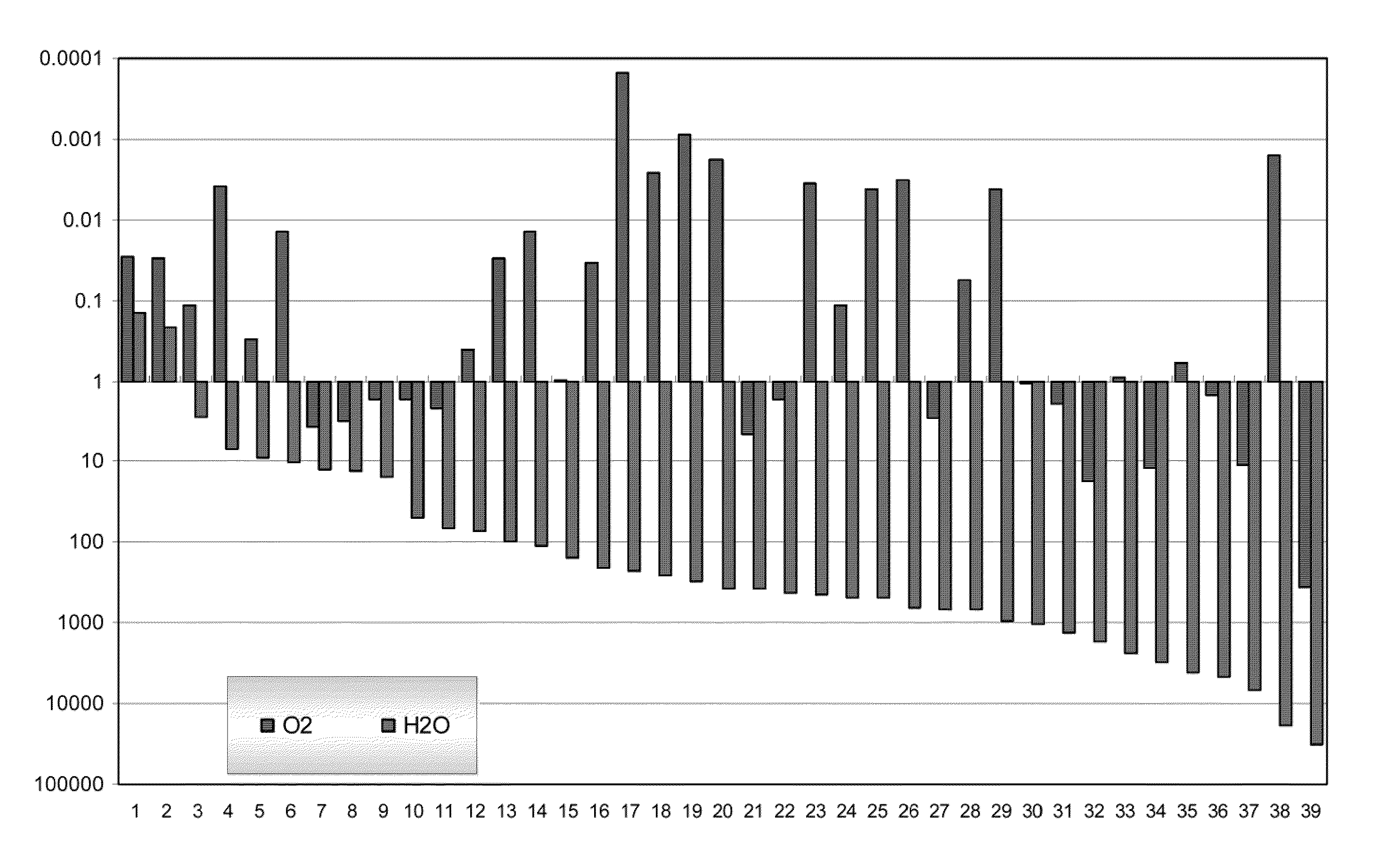
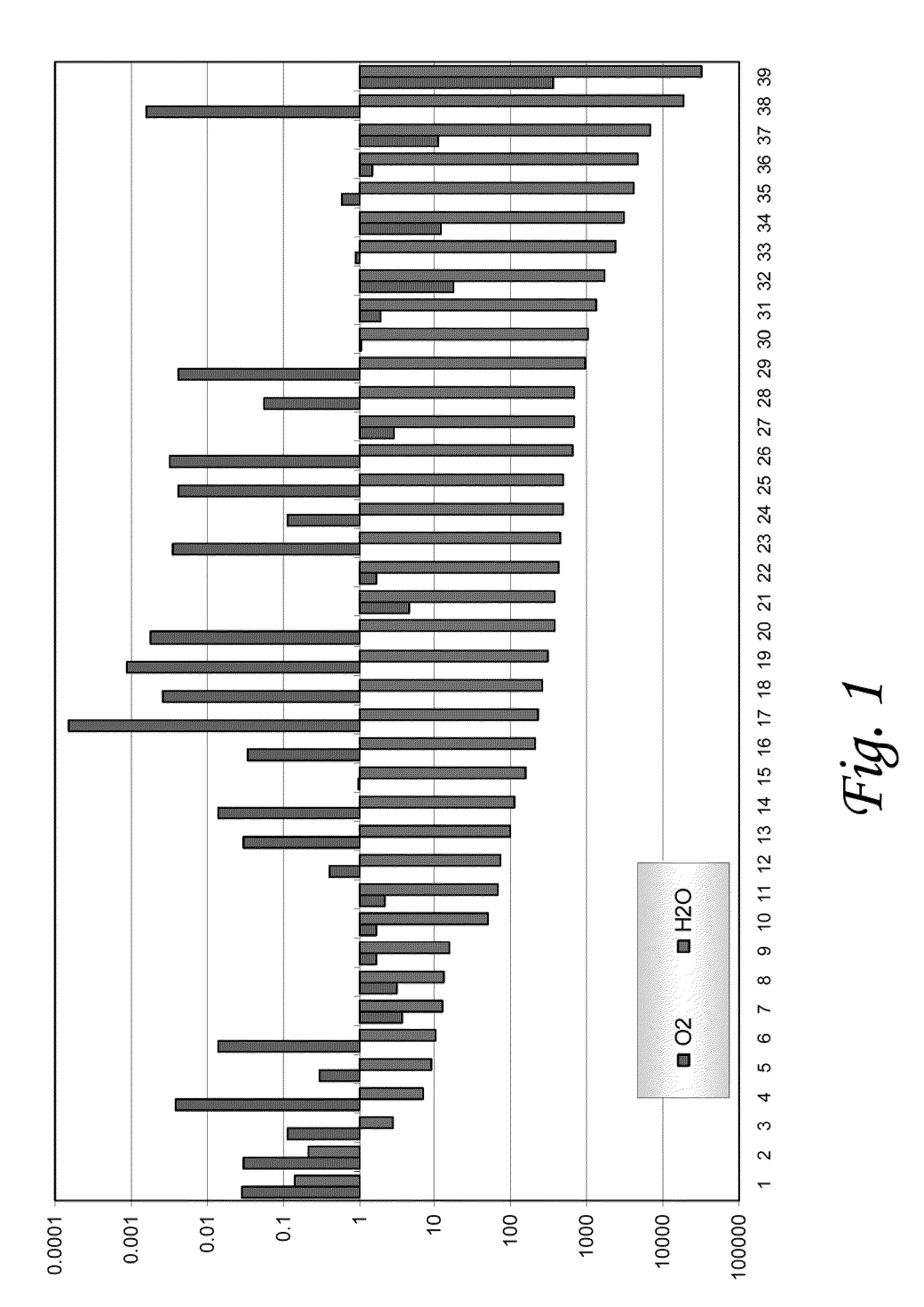
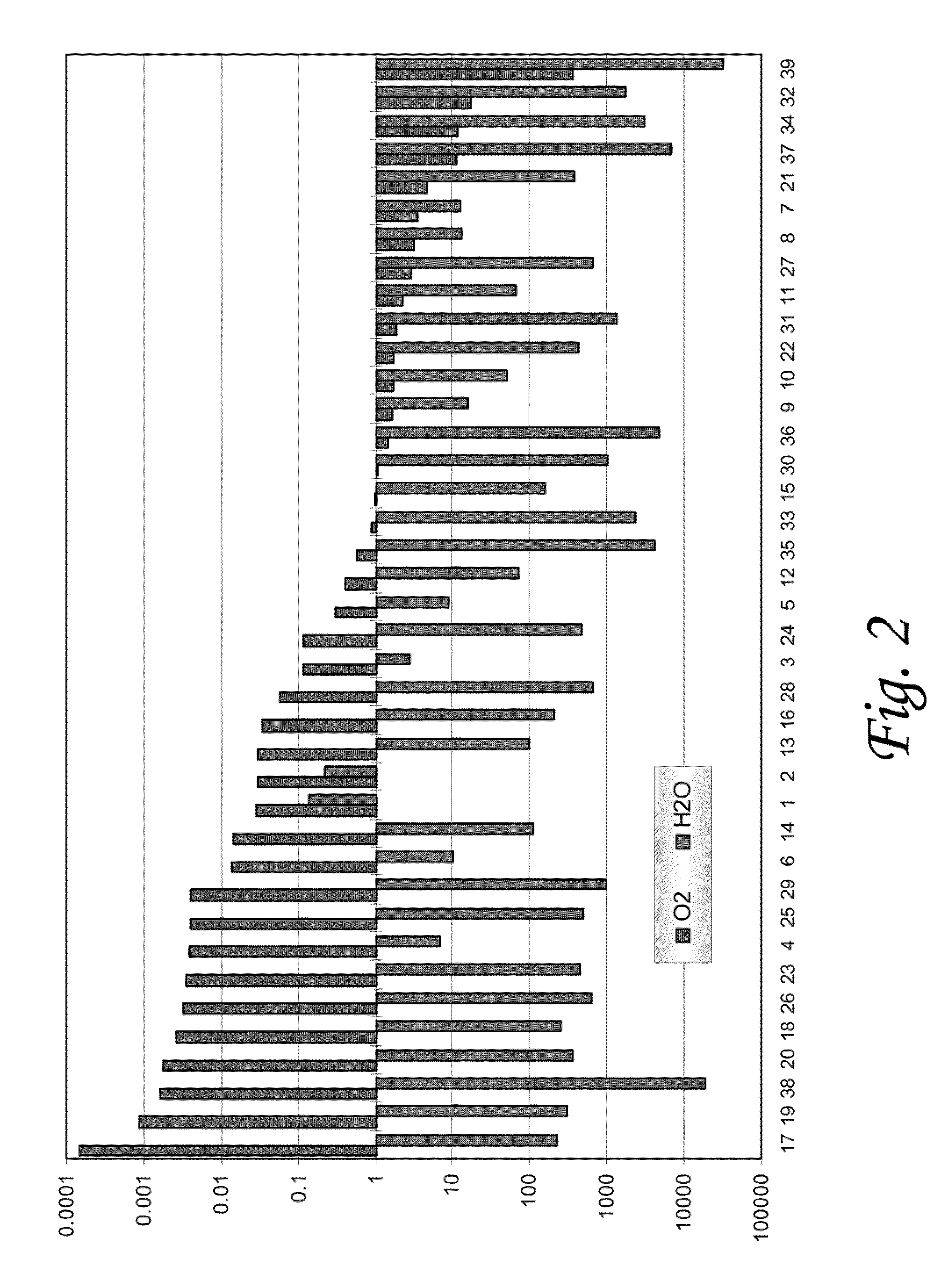
[0010]According to various embodiments of the invention thermal paste materials are provided. These materials can be used, in some embodiments as a thermal interface material. Embodiments of the invention can be configured to provide thermal stability and good reliability upon highly accelerated stress test (HAST) treatment. Embodiments of the materials are thermally stable in air and moist

Problems solved by technology

A critical issue is that the heat generated from these devices should be promptly and adequately removed to avoid overheating and subsequent damage to the devices.
However, upon extended use and over time, these greases can degrade, resulting in higher thermal resistance at the interface.
This impairs the transfer of heat away from the semiconductor device.
This problem has been attributed to two main causes which are sometimes referred to as “pump-out” and “dry-out.” The powering up and down of the devices caus

Method used


Image

  • Thermal interface materials with good reliability
  • Thermal interface materials with good reliability
  • Thermal interface materials with good reliability

Examples


example 1

Thermal Measurement and Reliability Test

[0037]Thermal resistance measurements of the materials are carried out on a thermal test vehicle (TTV) which simulates the CPU heat dissipation structures. The CPU is a silicon chip embedded with heating elements and temperature probes. Between the silicon wafer and the heat sink is one layer of thermal interface material of initial 4 mil thickness, the setup is secured with 65 psi pressure with screw tight.

[0038]The reliability test is normally conducted by putting the sample, which is mounted, in the TTV test device in an oven at a given temperature, or in a humidity chamber or temperature cycling chamber.

example 2

Materials and Sample Preparation

[0039]One example for the preparation of sample 1 is as follows: 100 g of hydrogenated olefin, which presents a low permeability to water is mixed with 60 g poly(imino-1-oxaundecamethylene) nylon 6 and 20 g of polytetrafluorethylene powder, which present low permeability to oxygen. To ensure homogenous mixing, heating may also be applied. To the above mixture 5 g of antioxidant is added, such as Ethanox 310, and a thixotropic agent such as Thixatrol Plus is also added. The filler materials for the thermal paste used are indium tin powders, which can account for as much as 85% of the weight of the paste.

[0040]As a comparison, sample 2 uses only polyol ester such as Hatcol 5150 as a suspension liquid to disperse the same metal filler.

[0041]Sample 3 is the commercially available thermal paste materials of Arctic Silver 5.

example 3

Materials Performance—Thermal Acing

[0042]Thermal aging experiments are conducted and the test results are shown in Table 3. It is shown that the sample 1 is much more stable than samples 2 and 3.

TABLE 3Aged at 90° C.Thermal resistance (cm2 K / W)(hours)Sample 1Sample 2Sample 300.1400.1420.1505000.1430.1870.20110000.1450.2100.252


PUM

PropertyMeasurementUnit
Volumeaaaaaaaaaa
Volumeaaaaaaaaaa
Temperatureaaaaaaaaaa

Abstract

A composition for a highly reliable thermal interface materials includes: (A) moisture-resistant polymer with a water permeability coefficient preferably less than 10−11 cm3 (STP) cm/cm2 S Pa, (B) gas barrier polymer having oxygen permeability coefficient preferably less than 10−14 cm3 (STP) cm/cm2 S Pa, (C) antioxidant, (D) thermal conductive filler and (E) other additive or optional materials. The thermal interface materials placed in between the thermal generating and dissipating devices can effectively barrier water and oxygen penetration, preventing the thermal fillers from degradation and improving the reliability of the devices.

Description

RELATED APPLICATION[0001]This application claims the benefit of U.S. Provisional Application No. 61 / 330,220, which was filed on Apr. 30, 2010 and which is hereby incorporated herein by reference in its entirety.TECHNICAL FIELD[0002]The present invention relates generally to thermal interface materials, and more particularly, some embodiments relate to polymer-based thermal interface materials for use in integrated circuit applications.DESCRIPTION OF THE RELATED ART[0003]Increased demand for smaller, faster and more powerful electronic products using integrated circuits has driven the development of more powerful and smaller semiconductor devices. A critical issue is that the heat generated from these devices should be promptly and adequately removed to avoid overheating and subsequent damage to the devices. Heat management devices such as integrated heat sinks or heat pipes are normally used to spread the heat away from power generating devices. Between the heat sink and the semicon...

Claims


Application Information

Patent Timeline
IPC IPC(8): F28F7/00B23P15/00C09K5/00
CPCC09K5/14H01L23/3737H01L2924/3011Y10T29/49826H01L2924/0002H01L2924/00B32B27/08
Inventor CHEN, SIHAILEE, NING-CHENG
Owner INDIUM CORPORATION
Why Eureka
Try Eureka