True time delay phase array radar using rotary clocks and electronic delay lines

a phase array radar and rotary clock technology, applied in the field of truetime broadband phase array antenna systems, can solve the problems of complex beam pattern formation, limited array usability in some applications, and limited constructive interference pattern adjustment through the use of element distances, etc., to achieve the effect of easy and quick movemen

Active Publication Date: 2012-02-16
ANALOG DEVICES INC
View PDF0 Cites 246 Cited by
  • Summary
  • Abstract
  • Description
  • Claims
  • Application Information

AI Technical Summary

Benefits of technology

[0020]One advantage of the present invention is that beams for an antenna array can be precisely formed because a plurality of phases is available over a large area from an array of rotary oscillators. The invention thus supports selection of arbitrary phase at each antenna element allowing for very complex beam patterns, including multiple beams and beams with nulls.
[0021]Another advantage is that a beam can be easily and quickly moved to a new azimuth and elevation by selecting among the available phases and cycle counts from an array of rotary oscillators.
[0022]Yet another advantage is that an antenna element can be operative in the array for a large number of clock cycles while the local oscillator used by that element maintains a precise phase shift.
[0023]Yet another embodiment of the present invention is an antenna element circuit for providing a true time delay. The antenna element circuit includes an rf port for sending or receiving rf signals, an antenna element port for connecting to an antenna element, a transmit path, a receive path, a local multiphase oscillator, and a pair of switches. The transmit path is the path through which a signal to be transmitted travels to an antenna element and includes an analog delay line for time delaying an if signal on the rf port in response to transmit delay line timing signals, a S/H circuit connected to the analog delay line for adding a fractional delay to the delayed rf signal in response to a transmit sample and hold timing signal, and a power amplifier for boosting the signal from the S/H circuit and for driving the antenna element. The receive path is the path through which a received signal travels from an antenna element and includes a low noise amplifier for boosting the received signal, a S/H circuit, connected to the low noise amplifier, for adding a fractional delay to the received

Problems solved by technology

Adjusting the constructive interference patterns by means of the element distances is generally limited.
If the distances between elements are equal or greater than the wavelength, then undesirable grating lobes are formed, and the array is not usable in some applications.
Not only can the beam be moved, but

Method used


Image

  • True time delay phase array radar using rotary clocks and electronic delay lines
  • True time delay phase array radar using rotary clocks and electronic delay lines
  • True time delay phase array radar using rotary clocks and electronic delay lines

Examples


example timing

of Phase Array System

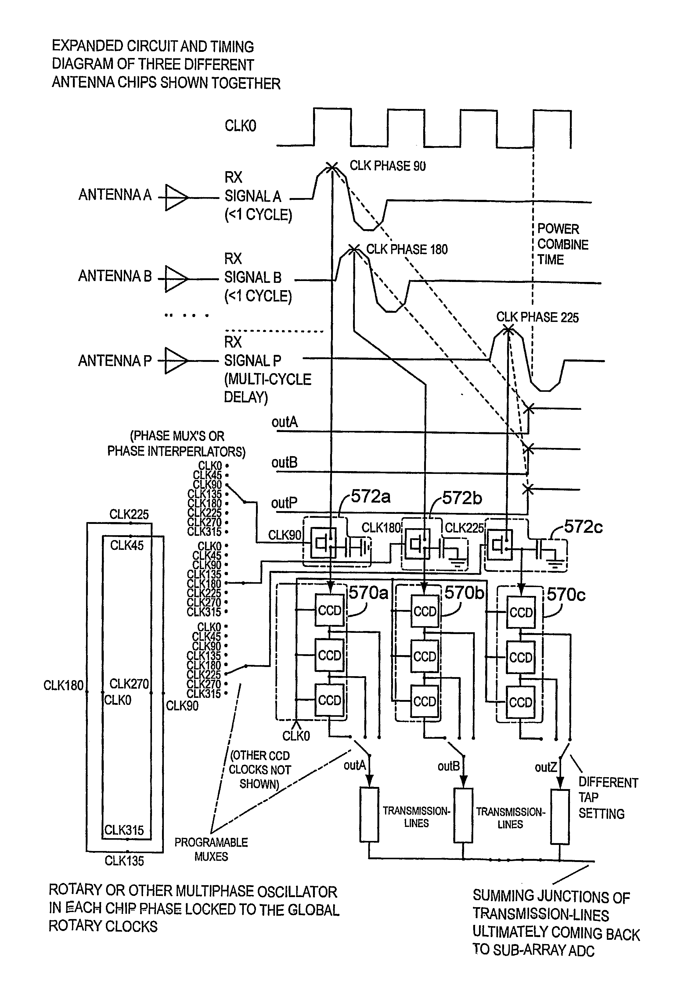
[0120]FIG. 19 shows an exploded circuit diagram of three antenna switches chosen from an X / Y array and is shown flat as one circuit. (In practice, there many individual chips physically separated and the diagram would be hierarchical). The Receive path is shown but the TX is similar in principle with all the signal directions reversed (through muxing).

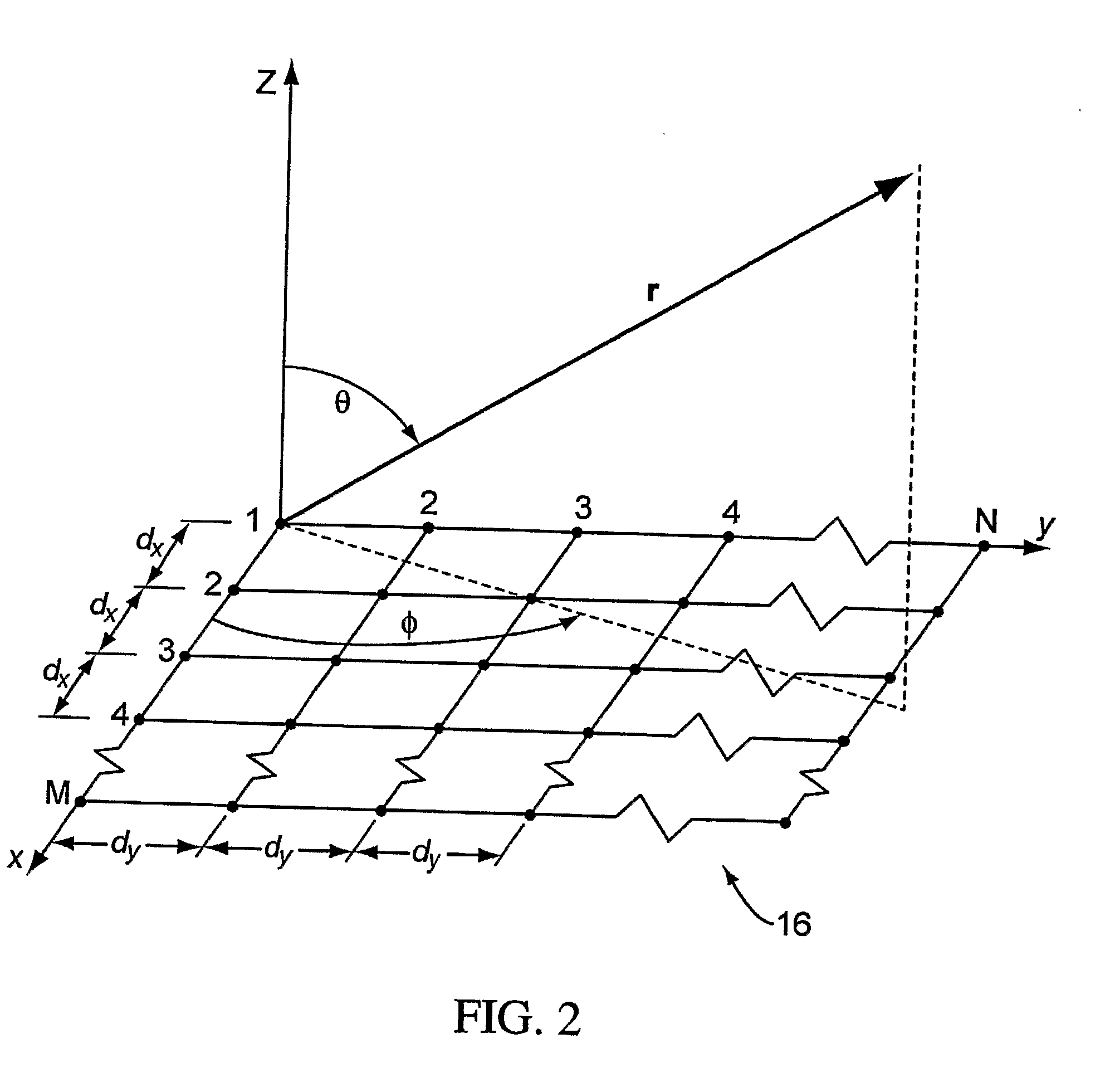
[0121]FIG. 20 depicts the topology of the example array of 16 elements shown with a single-pulse radar echo arriving from north-east of the array. Antenna integrated circuit A receives the signal first, element B receives the signal a short time later. Element P receives the pulse at an even later time.

[0122]FIG. 19 has a timing diagram showing the phase-select settings for the S / H and the CCD tap settings that achieve the correct true-time power combination. A combination of S / H selectable phase and a pipelined CCD storage element 570a,b,c with selectable taps gives the equivalent of a programmable delay line for ...


PUM


Abstract

Local oscillator circuitry for an antenna array is disclosed. The circuitry includes an array of rotary traveling wave oscillators which are arranged in a pattern over an area and coupled so as to make them coherent. This provides for a set of phase synchronous local oscillators distributed over a large area. The array also includes a plurality of phase shifters each of which is connected to one of the rotary oscillators to provide a phase shifted local oscillator for the array. The phase shifter optionally includes a cycle counter that is configured to count cycles of the rotary oscillator to which it is connected and control circuitry that is then operative to provide a shifted rotary oscillator output based on the count from the cycle counter. A system and method for operating a true-time delay phased array antenna system. The system includes a plurality of antenna element circuits for driving or receiving an rf signal from the elements of the array. Each element circuit has a transmit and a receive path and a local multiphase oscillator, such as a rotary traveling wave oscillator. Each path has an analog delay line for providing a true-time delay for the antenna element. Preferably, the analog delay line is a charge coupled device whose control nodes are connected to phases of the local multiphase oscillator to implement a delay that is an integer number local multiphase oscillator periods. A fractional delay is also included in the path by using a sample and hold circuit connected to a particular phase of the oscillator. By delaying each antenna element by a true time delay, broadband operation of the array is possible.

Description

CROSS-REFERENCE TO RELATED APPLICATIONS[0001]This application claims priority to U.S. Provisional Application Ser. No. 60 / 688,169, filed Jun. 6, 2005, titled “PHASED ARRAY ANTENNA SYSTEMS USING ROTARY TRAVELING WAVE OSCILLATORS,” which is incorporated by reference into the instant application and priority to U.S. Provisional Application Ser. No. 60 / 730,915, filed Oct. 26, 2005, and titled “TRUE TIME DELAY PHASE ARRAY RADAR USING ROTARY CLOCKS AND ELECTRONIC DELAY LINES”, which is incorporated by reference into the instant application.FIELD OF THE INVENTION[0002]The present invention relates generally to broadband phased array antenna systems and more particularly to true-time broadband phase array antenna systems.DESCRIPTION OF THE RELATED ART[0003]Antenna arrays are well-known and operate according to the general principle that the far field of an array of identical elements is the product 10 of the electric field pattern of a single element 12 considered as a point source at a ref...

Claims


Application Information

Patent Timeline
IPC IPC(8): H01Q21/00H03H11/26H04B1/40H03L7/24
CPCG01S7/03G01S13/0209H01Q3/2694H01Q3/42G01S2007/4034G01S2007/403G01S7/4034G01S7/403H03B5/1852
Inventor WOOD, JOHNBASIT, HARIS
Owner ANALOG DEVICES INC
Why Eureka
Try Eureka