Thermal evaporation process for manufacture of solid state battery devices

Active Publication Date: 2012-03-08
SAKTI3
View PDF7 Cites 50 Cited by
  • Summary
  • Abstract
  • Description
  • Claims
  • Application Information

AI Technical Summary

Benefits of technology

[0016]Benefits are achieved over conventional techniques. In one or more embodiments, the present method and device uses conventional techniques, which are easy to implement in an efficient and cost effective manner. Additionally, the present method provides for a scalable process for high throughput cell manufacturing. The use of ion beam for tuning the layer properties does not affect the high rate deposition from the flash process that provides an ideal solution for continuous roll-to-roll process. Accordingly, we have been able to systematically produce a cost effective design and manufacturing process to meet performance targets such as performance, reliability, safety, lifecycle, reclamation and reuse, cost, and other factors. Depending upon the specific embodiment, one or more of

Problems solved by technology

However, these amorphous or crystalline intercalation compounds often have insufficient ionic/electronic conductivity to be used in battery electrodes alone.
The use of composite electrodes has been one of the key problems to Li-ion battery researchers as it is linked to battery failure mechanisms.
The inhomogeneous mixture in the electrode caused non-uniform charge distribution and localized stress and heat generation, often leads to the limited cycle life of batteries.
Furthermore, addition of binder and conductive materials reduce energy density of the battery.
However, the deposition rate from sputtered LiPON is limited to only 1-2 Å/s.
Other techniques using higher energy sources, such as electron beam evaporation attempt to achieve higher deposition rate, but their y

Method used


Image

  • Thermal evaporation process for manufacture of solid state battery devices
  • Thermal evaporation process for manufacture of solid state battery devices
  • Thermal evaporation process for manufacture of solid state battery devices

Examples


Embodiment Construction

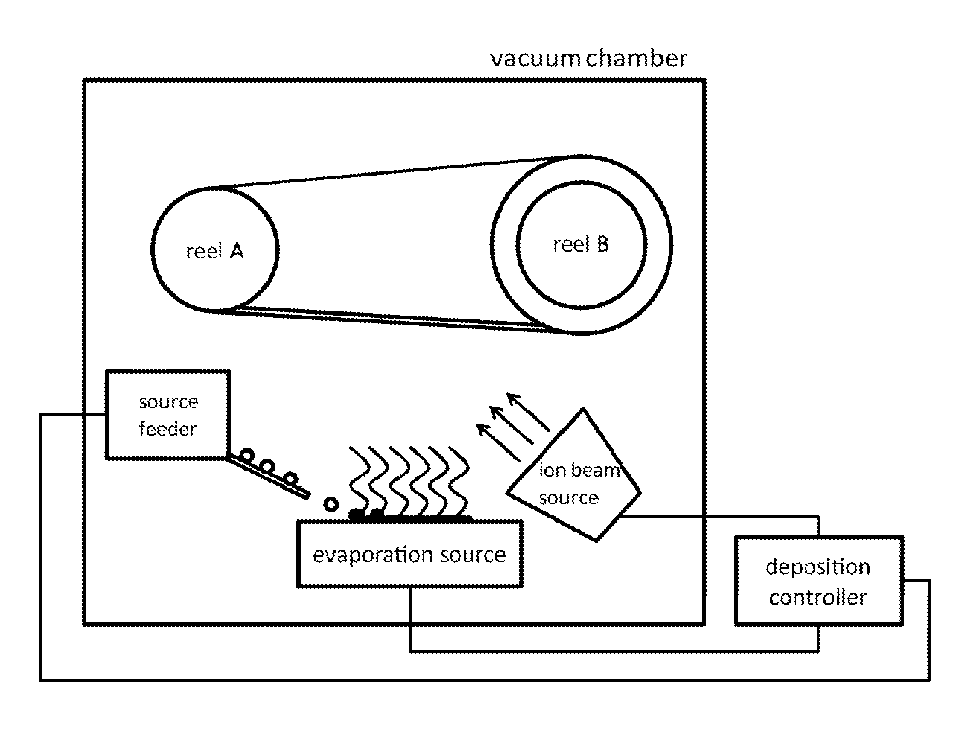
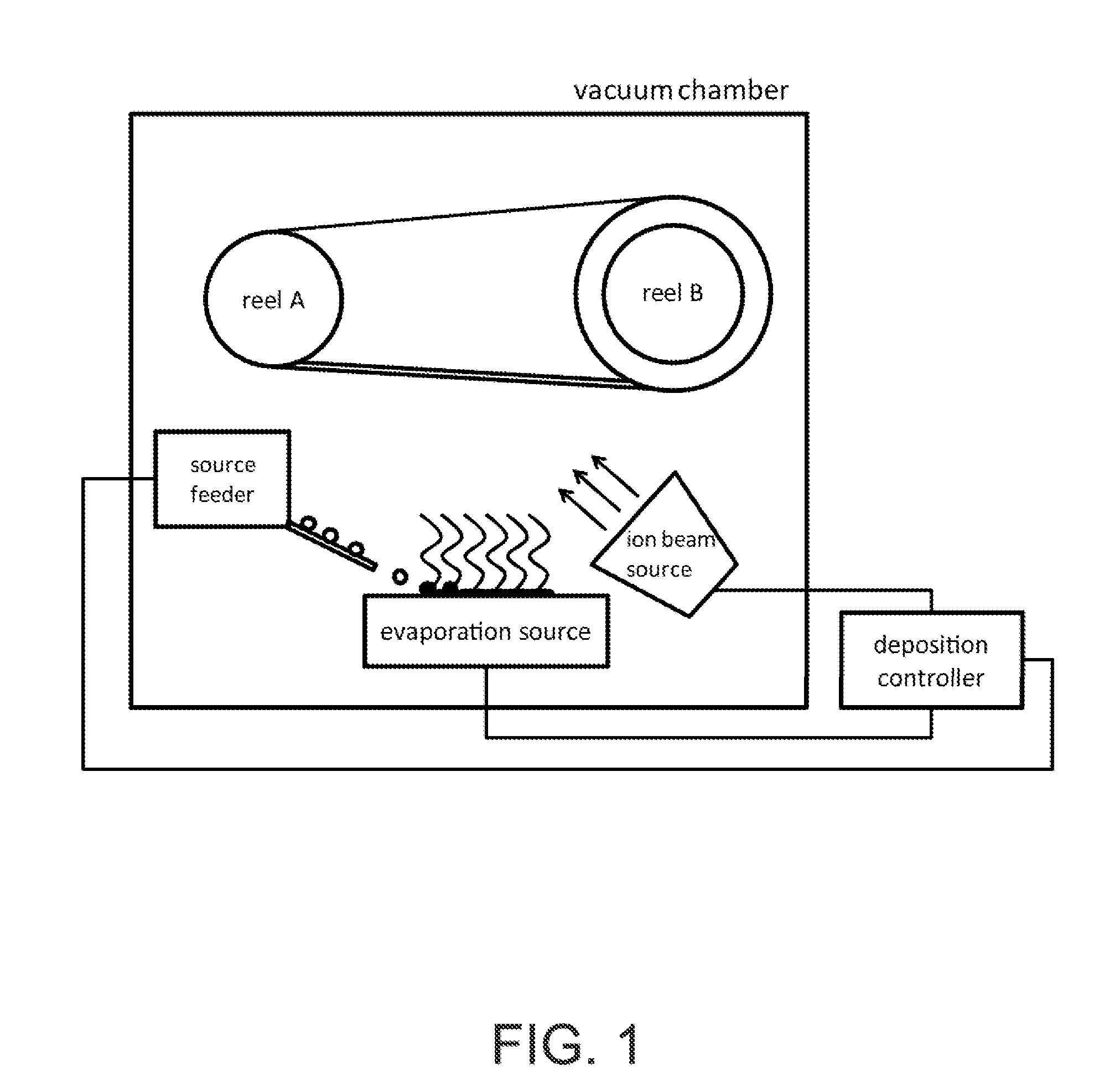
[0028]According to the present invention, processing techniques related to manufacture of solid-state electrochemical cells are provided. More particularly, the present invention provides methods for manufacture of electrodes (cathode and anode) and electrolyte materials by flash evaporation processes for continuous roll-to-roll production, and ion-beam assisted processes for adjusting the required layer properties.

[0029]Merely by way of example, the invention has been provided with a vacuum system configured for a multiple pass roll-to-roll coater, in which a substrate is coated with a sequence of steps by changing in direction of the movement of the substrate within a single vacuum chamber. In an alternative approach, the substrate may be moved in the same direction around the reels as a single pass deposition process, with conditions within the chamber periodically changed to result in the continuous build-up of deposited material over time. Alternatives can also be provided wher...


PUM

PropertyMeasurementUnit
Fractionaaaaaaaaaa
Fractionaaaaaaaaaa
Timeaaaaaaaaaa

Abstract

A method for manufacturing a solid-state battery device. The method can include providing a substrate within a process region of an apparatus. A cathode source and an anode source can be subjected to one or more energy sources to transfer thermal energy into a portion of the source materials to evaporate into a vapor phase. An ionic species from an ion source can be introduced and a thickness of solid-state battery materials can be formed overlying the surface region by interacting the gaseous species derived from the plurality of electrons and the ionic species. During formation of the thickness of the solid-state battery materials, the surface region can be maintained in a vacuum environment from about 10-6 to 10-4 Torr. Active materials comprising cathode, electrolyte, and anode with non-reactive species can be deposited for the formation of modified modulus layers, such a void or voided porous like materials.

Description

BACKGROUND OF THE INVENTION[0001]This present invention relates to manufacture of electrochemical cells. More particularly, the present invention provides a method and resulting device for forming elements of a thin film solid-state electrochemical cell. Merely by way of example, the invention has been provided with use of lithium based cells, but it would be recognized that other materials such as zinc, silver, copper and nickel could be designed in the same or like fashion. Additionally, such batteries can be used for a variety of applications such as portable electronics (cell phones, personal digital assistants, music players, video cameras, and the like), power tools, power supplies for military use (communications, lighting, imaging and the like), power supplies for aerospace applications (power for satellites), and power supplies for vehicle applications (hybrid electric vehicles, plug-in hybrid electric vehicles, and fully electric vehicles). The design of such batteries is ...

Claims


Application Information

Patent Timeline
IPC IPC(8): H01M4/04C23C16/56C23C16/06C23C16/448C23C16/40C23C16/48H01M50/403
CPCC23C14/0031C23C14/0676C23C14/083H01M2/145H01M4/0423H01M10/0585H01M4/48H01M4/483H01M4/5825H01M6/40H01M10/0562H01M4/382Y02E60/10H01M50/403Y02P70/50C23C14/5833H01M4/131H01M4/1391H01M2004/028
Inventor CHUNG, MYOUNGDOKIM, HYONCHEOLSASTRY, ANN MARIELANGLOIS, MARC
Owner SAKTI3
Why Eureka
Try Eureka