

High-pressure quartz crystal microbalance
a quartz crystal and microbalance technology, applied in the direction of instruments, specific gravity measurement, machines/engines, etc., can solve the problems of large sample amounts, inability to measure gas adsorption in thin films or coatings, and high capital and operating costs of the company, so as to improve the accuracy and reliability of the device, accurately control the gas influx, and accurately ascertain the important parameters
- Summary
- Abstract
- Description
- Claims
- Application Information
AI Technical Summary
Benefits of technology
Problems solved by technology
Method used
Image

Examples
example 1
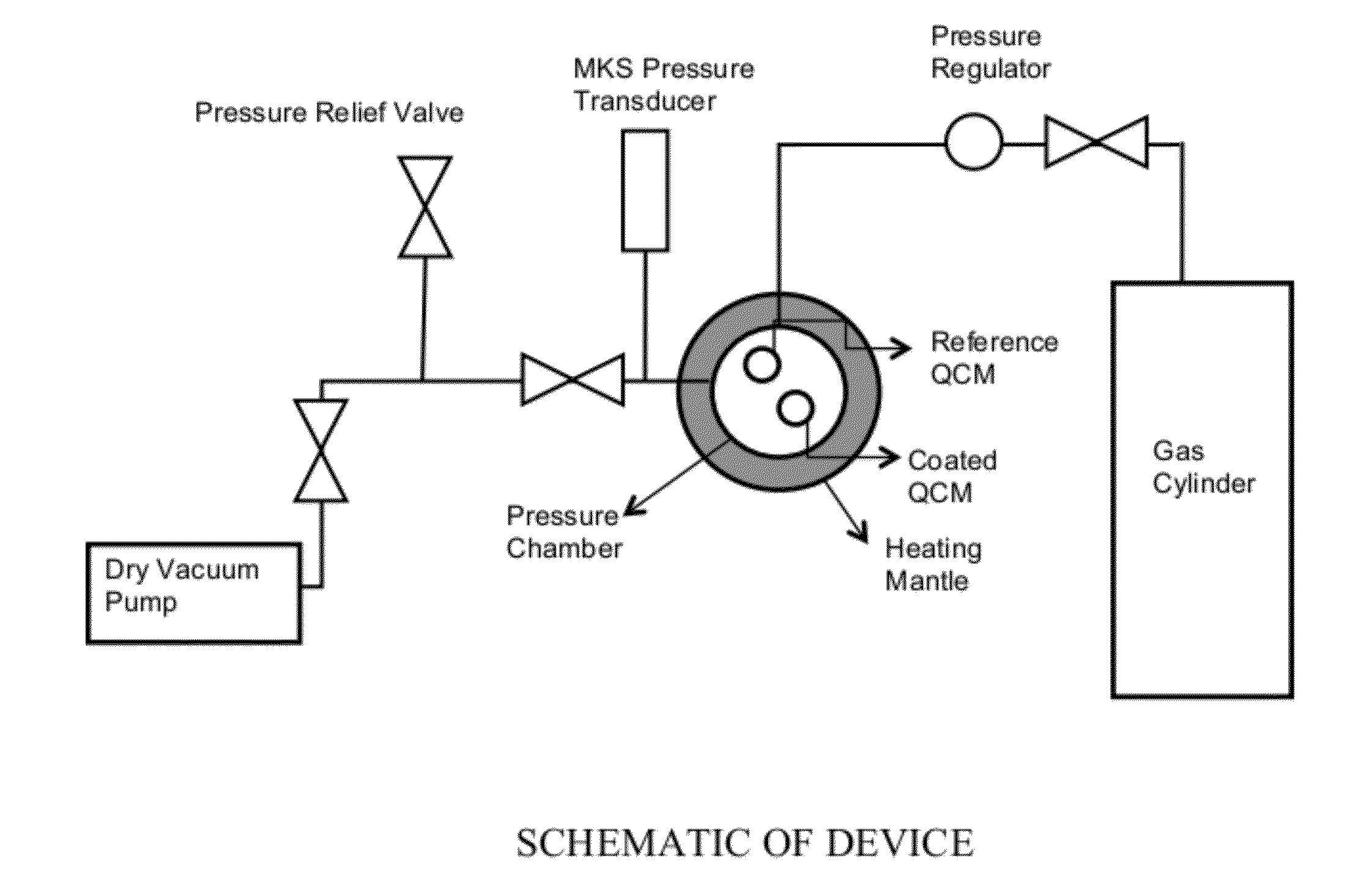
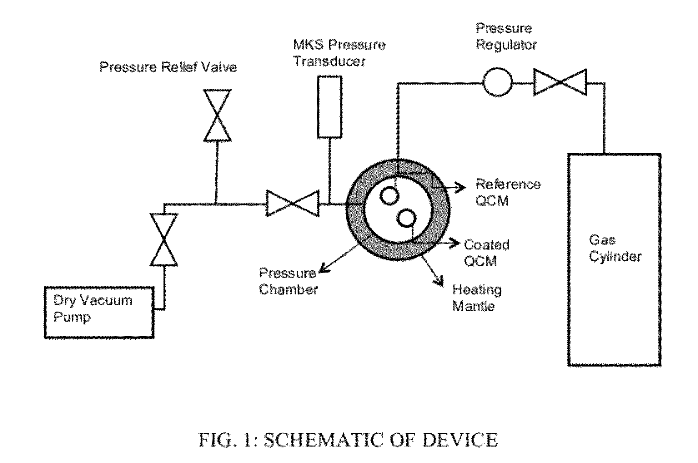
[0061]FIG. 1 shows a schematic of a QCM measurement setup according to the invention. Simply speaking, the pressure chamber (aka sample chamber) contains two QCMs—a coated QCM and a reference QCM. The chamber is insulated, capable of withstanding high pressures, and is provided with a heating mantle or similar device for controlling temperature therein. A gas cylinder is fluidly connected to the chamber, and feeds gas into the chamber as needed. A pressure regulator and valves control the input of gas. Because pressure also needs to be tightly controlled, the chamber is fluidly connected to a pressure transducer and pressure relief valves. A vacuum pump is also fluidly connected thereto.
[0062]In our test experiments, the QCMs were purchased from Inficon, NY. They had a resonant frequency of 5 MHz, were cut at room temperature, and had polished gold electrodes on both sides. Two identical crystals were placed inside a 175 ml high pressure stainless steel cylindrical chamber with a cu...
example 2
[0068]The system of the present invention is capable of measuring single-component gas adsorption under a high pressure environment. The gas was fed from the gas tank and flowed through the safety check valve and the release / leak valve before entering the high pressure cell, where the adsorption of the gas to the MOF takes place. The pressure inside the high pressure cell was monitored by the pressure sensor and was adjusted accordingly. After the isotherm measurement was completed, the gas can be exhausted either to the atmosphere or through the vacuum pump. Optionally, a volume controlling means, for example a flow meter (not shown), is connected to an inlet (not shown) of the high pressure cell in order to control the amount of gas being introduced.
[0069]The pressure cell shown in the schematic is a cylindrical chamber of a volume of 170 cm3. The QCMs used in this experiment were room temperature cut QCM. For this experiment, a reference QCM and a MOF coated QCM were inserted int...
example 1a
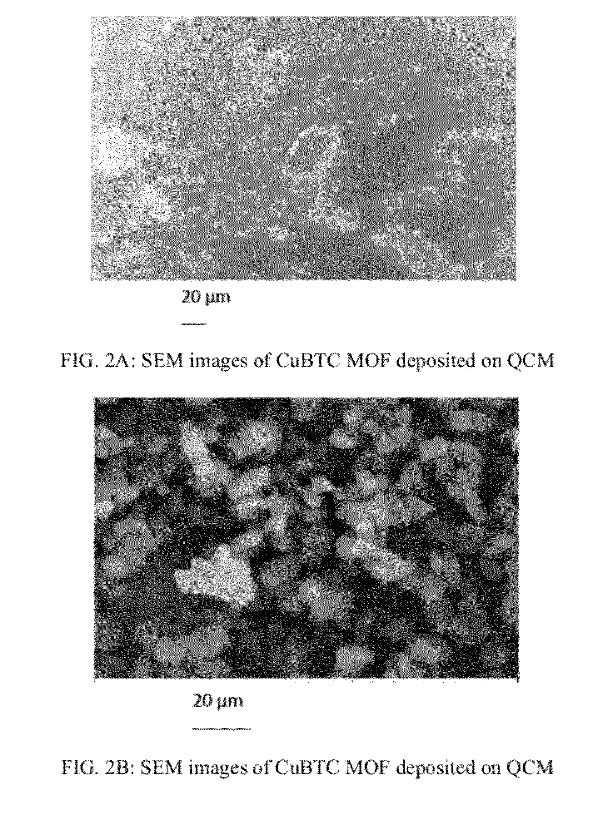
[0070]Prior to conducting these experiments, SEM images and XRD patterns of the MOF-coated samples were obtained and shown in FIG. 2A-2F. These characterizations confirm that the MOF particles were indeed dispersed on the surface of the QCM and that they retain the expected crystal structure.
[0071]The CuBTC(HKUST-1) sample was deposited on INFICON AT-cut quartz at 25° C. The sample was preheated at 120° C. for 9 hours, followed by forced convection cooling to 21° C.
[0072]The results of two experimental adsorption and desorption under high pressure, as well as corresponding Langmuir adsorption and desorption isotherm curves, are shown in FIG. 3A for CuBTC(HKUST-1). The experimental procedure began with initial preheating of the pressure cell with the MOF coated QCM and reference uncoated QCM to a temperature of 105° C. at a pressure of 0.59 psi to remove the moisture present in the MOFs. The system, however, is capable of attaining even higher temperatures. Since the MOFs were deposi...
PUM
 Abstract
Description
Claims
Application Information