Ion substituted calcium phosphate coatings

a technology applied in the field of methods, can solve the problems of limited clinical application of ion substituted ceramics and cements, chemical defects, and relatively thick and brittle coatings

Inactive Publication Date: 2012-04-12
BIOMATCELL
View PDF1 Cites 8 Cited by
  • Summary
  • Abstract
  • Description
  • Claims
  • Application Information

AI Technical Summary

Benefits of technology

[0034]Another aspect of the present invention is an ion substituted coating comprising calcium, magnesium, phosphate and one or more o

Problems solved by technology

Despite the beneficial results, the clinical application of ion substituted ceramics and cements is limited due to low mechanical strength.
For example, the coatings are relatively thick and brittle, and also possess chemical defects.
They do not always adhere well to the substrates.
Furthermore, such coatings could not be evenly and uniformly applied to surfaces with complex geometri

Method used


Image

  • Ion substituted calcium phosphate coatings
  • Ion substituted calcium phosphate coatings
  • Ion substituted calcium phosphate coatings

Examples


example 1

Deposition of Strontium Substituted Calcium Phosphate Coating on Heat Treated Titanium Surfaces

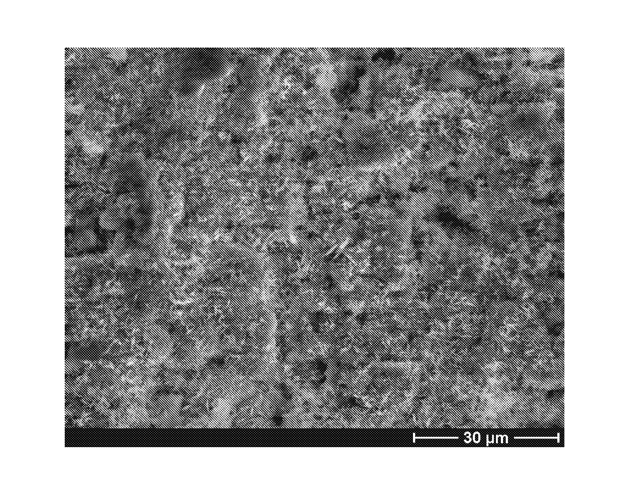
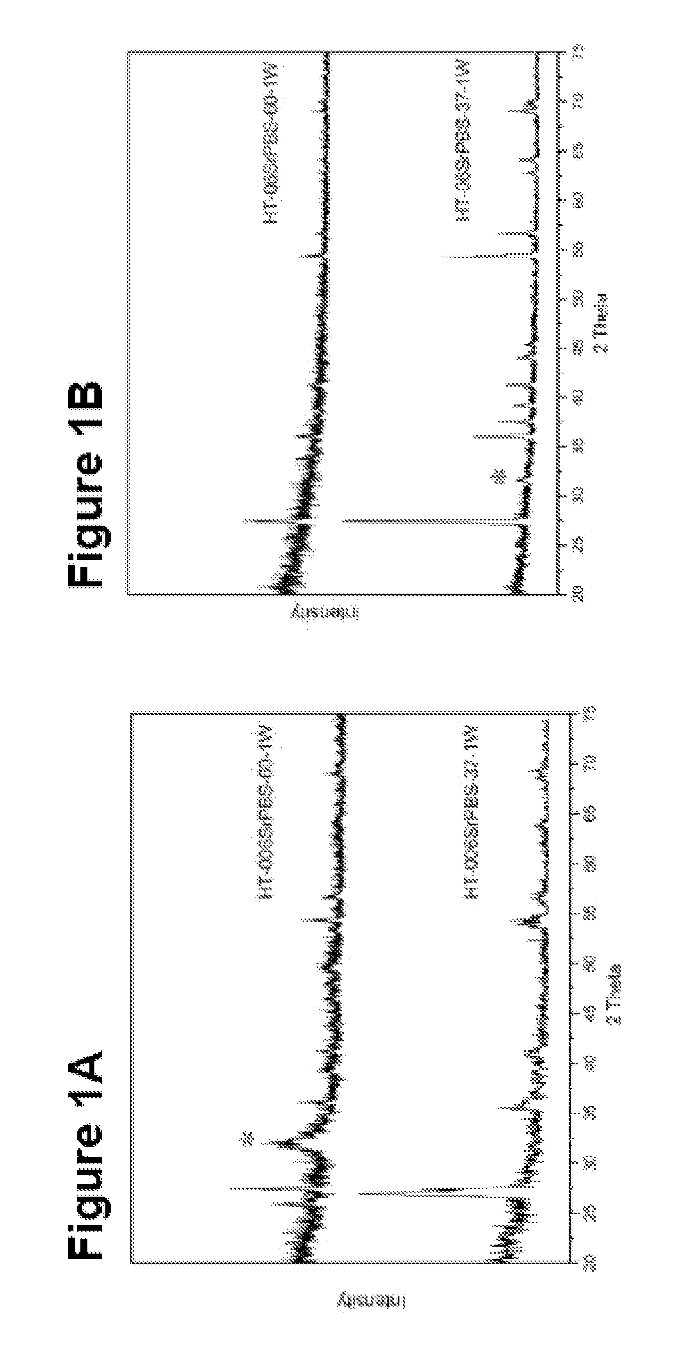
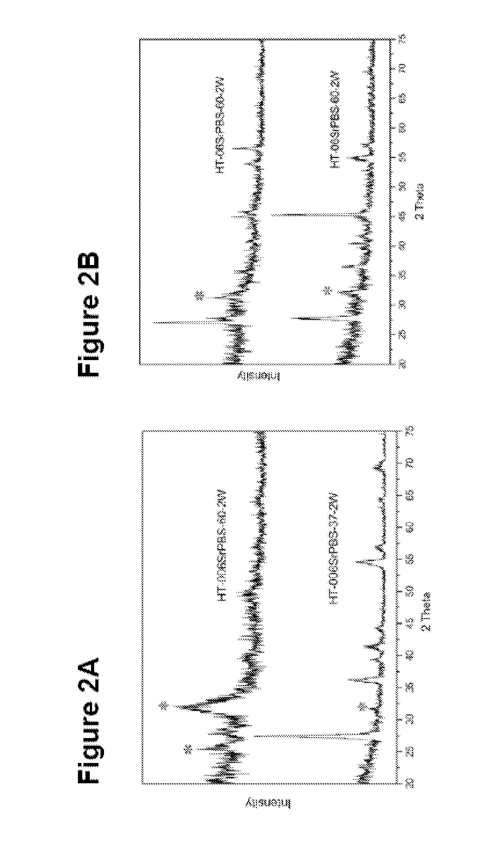
[0118]10 mm×10 mm titanium plates were treated using heat treatment (at 800° C. for 2 hours) to get titanium dioxide surface. The treated plates were first cleaned ultrasonically in acetone, followed in ethanol, and finally rinsed with de-ionized water and dried at 37° C. Two kinds of mineralizing solutions were obtained from the modified phosphate buffer solution (PBS) (see table 2). The low concentration of Sr PBS was 0.06 mmol / l. The high one was 0.6 mmol / l. The initial pH of the low one was 7.20 and 7.21 at 37° C. and 60° C., respectively. The initial pH of the high one was 7.19 and 7.15 at 37° C. and 60° C., respectively. Every two specimens were soaked into 40 ml preheated solution in a sealed plastic bottle, which were then put into the oven at 37° C. and 60° C., respectively. The plates were incubated for different time periods from 1 week to 2 weeks. All specimens were then rinsed...

example 2

Deposition of Strontium Substituted Calcium Phosphate Coating on PVD Treated Titanium Surfaces

[0120]The coating process was similar to example 1 but the substrates were PVD treated titanium plates.

[0121]The PVD treatment was as following:

[0122]The titanium plates were placed in a PVD chamber (Baltzer 640R). The magnetron effect and the oxygen partial pressure during the coating step were 1.5 kW and 1.5×10⁻³ mbar, respectively. The setup of the PVD apparatus was optimised for maximum production of the rutile structure in the TiO2 film. The results are shown in FIGS. 10-16.

example 3

Deposition of Silicon Substituted Calcium Phosphate Coating on PVD Treated Titanium Surfaces

[0123]10 mm×10 mm titanium plates were treated using PVD treatment as described in Example 2 to get titanium dioxide surface. The treated plates were first cleaned ultrasonically in acetone, followed in ethanol, and finally rinsed with de-ionized water and dried at 37° C. The mineralizing solution containing silicate was obtained from the modified phosphate buffer solution (PBS). The modified PBS was prepared as the following:[0124](1) 3 mg tricalcium silicate was added into 40 ml PBS solution stirred overnight.[0125](2) The turbid solution was then centrifuged, and the supernatant solution was acted as the mineralizing medium.[0126](3) The pH value and composition of the solution were analyzed by pH meter and ICP-AES, respetively.

[0127]Every two specimens were soaked into 40 ml preheated solution in a sealed plastic bottle, which were then put into the oven at 60° C. for 1 week. All specimen...


PUM

PropertyMeasurementUnit
Temperatureaaaaaaaaaa
Fractionaaaaaaaaaa

Abstract

A method for the formation of a surface coating of an ion substituted calcium phosphate on a substrate, the coating itself and the use of the coating.

Description

BACKGROUND OF THE INVENTION[0001]The present invention relates to a method for the formation of a surface coating, specifically a crystalline surface coating, of an ion substituted calcium phosphate on a substrate. The invention also relates to a ion substituted calcium phosphate surface coating produced by the method.[0002]Calcium phosphate in bone is a multi-substituted calcium phosphate, including traces of CO32−, F−, Cl−, Mg2+, Sr2+, Si4+, Zn2+, Ba2+, Fe3+, etc [1-3]. These ionic substitutions play an important role in bone formation and normal functions, such as the solubility and surface chemistry of the material.[0003]Carbonate (CO32−) is the most abundant (2-8 wt %) anionic substitute, and partially substitutes both in the PO43− site and the OH− site of the calcium phosphate structure. The high reactivity of young bone could be related to the greater presence of carbonate compared with old bone. Carbonated calcium phosphate has showed improved solubility, collagen deposition...

Claims


Application Information

Patent Timeline
IPC IPC(8): A61K33/42C23C16/44A61K9/00B05D3/10B05D3/02B05D5/00B05D3/06
CPCA61L2400/18A61L27/32
Inventor XIA, WEILINDAHL, CARLENGQVIST, HAKANTHOMSEN, PETERLAUSMAA, JUKKA
Owner BIOMATCELL
Why Eureka
Try Eureka