Method For Manufacturing Separator, Separator Manufactured By The Method And Method For Manufacturing Electrochemical Device Including The Separator

Active Publication Date: 2012-04-19
LG ENERGY SOLUTION LTD +1
View PDF5 Cites 16 Cited by
  • Summary
  • Abstract
  • Description
  • Claims
  • Application Information

AI Technical Summary

Benefits of technology

[0019]The separator manufactured by the method of the present invention exhibits the following advantageous effects.
[0020]First, the non-solvent sprayed on the slurry promotes phase separation of the second binder polymer to allow a larger amount of the second binder polymer to be distributed on the surface of the porous coating layer. This distribution enhances the bindability of the separator to electrodes, thus fa

Problems solved by technology

However, such lithium ion batteries suffer from safety problems, such as fire or explosion, when encountered with the use of organic electrolytes and have a disadvantage in that they are complicated to manufacture.
Overheating of an electrochemical device may cause thermal runaway or a puncture of a separator may pose an increased risk of explosion.
This thermal shrinkage behavior may cause short circuits between a cathode and an anode.
However, an increase in the content of the inorganic particles, i.e. a decrease in the content of the binder polymer, reduces the bind

Method used


Image

  • Method For Manufacturing Separator, Separator Manufactured By The Method And Method For Manufacturing Electrochemical Device Including The Separator
  • Method For Manufacturing Separator, Separator Manufactured By The Method And Method For Manufacturing Electrochemical Device Including The Separator

Examples


Example

Example 1

[0052]A polymer mixture of cyanoethylpullulan as a first binder polymer and polyvinylidene fluoride-co-hexafluoropropylene (PVdF—HFP) as a second binder polymer in a weight ratio of 2:10 was dissolved in acetone at 50° C. for at least about 12 hours to prepare a polymer solution. A barium titanate (BaTiO3) powder was added to the polymer solution until the weight ratio of the polymer mixture to the inorganic powder reached 10:90. The inorganic particles were crushed and dispersed using a ball mill for at least 12 hours to prepare a slurry. The inorganic particles of the slurry had an average particle diameter of 600 nm.

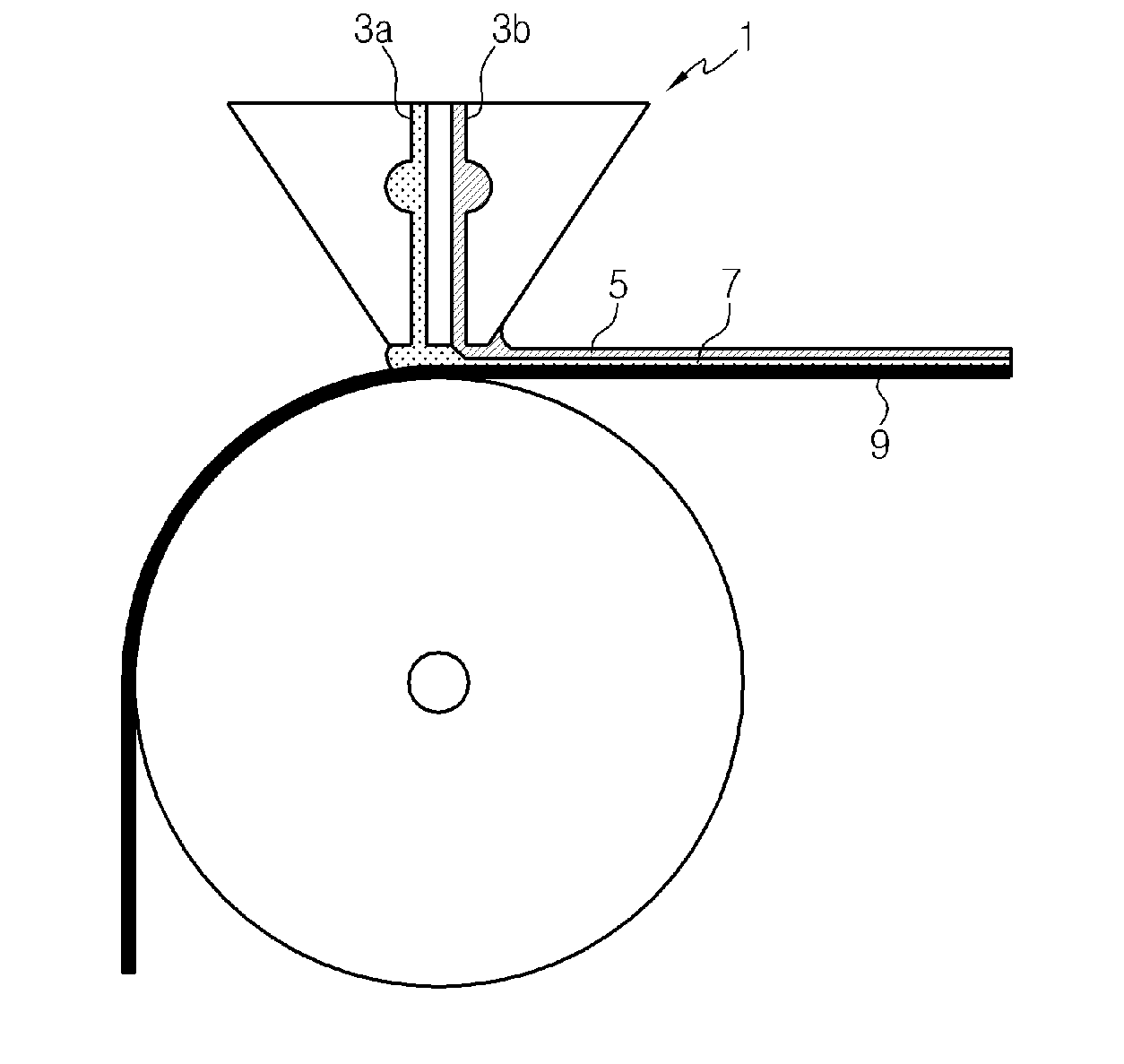
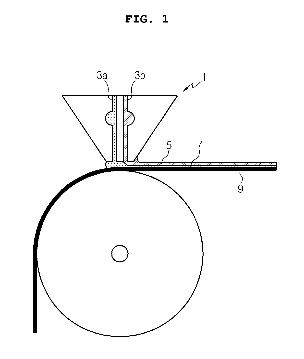
[0053]The slurry and distilled water as a non-solvent for the second binder polymer were sequentially coated on one surface of a 12 μm thick porous polyethylene terephthalate membrane (porosity 45%) through the slot die illustrated in FIG. 1. The wet thicknesses of the slurry and the non-solvent were adjusted to 75 μm and 10 μm, respectively.

[0054]Subsequentl...

Example

Example 2

[0057]A separator was manufactured in the same manner as in Example 1, except that the kind of the non-solvent was changed to a mixture of distilled water and methanol (5:5 (v / v)). The separator was found to have a Gurley value of 367.6 sec / 100 mL and a bonding strength of 9.81 gf / cm.

Example

Example 3

[0058]A separator was manufactured in the same manner as in Example 1, except that the kind of the first binder polymer was changed to polycyanoacrylate. The separator was found to have a Gurley value of 375.4 sec / 100 mL and a bonding strength of 13.94 gf / cm.


PUM

PropertyMeasurementUnit
Thicknessaaaaaaaaaa
Particle diameteraaaaaaaaaa
Weight ratioaaaaaaaaaa

Abstract

Disclosed is a method for manufacturing a separator. The method includes (S1) preparing a porous planar substrate having a plurality of pores, (S2) preparing a slurry containing inorganic particles dispersed therein and a polymer solution including a first binder polymer and a second binder polymer in a solvent, and sequentially coating the slurry on the porous substrate through a first discharge hole and a non-solvent incapable of dissolving the second binder polymer on the slurry through a second discharge hole adjacent to the first discharge hole, and (S3) simultaneously removing the solvent and the non-solvent by drying. According to the method, a separator with good bindability to electrodes can be manufactured in an easy manner. In addition, problems associated with the separation of inorganic particles in the course of manufacturing an electrochemical device can be avoided.

Description

CROSS-REFERENCE TO RELATED APPLICATION[0001]This application is a continuation of International Application No. PCT / KR2011 / 001370 filed Feb. 25, 2011, which claims priority under 35 USC 119(a) to Korean Patent Application Nos. 10-2010-0016989 and 10-2011-0016506 filed in the Republic of Korea on Feb. 25, 2010 and Feb. 24, 2011, respectively, the entire contents of which are incorporated herein by reference.TECHNICAL FIELD[0002]The present invention relates to a method for manufacturing a separator for an electrochemical device such as a lithium secondary battery, a separator manufactured by the method, and a method for manufacturing an electrochemical device including the separator. More specifically, the present invention relates to a method for manufacturing a separator in which an organic-inorganic composite porous layer composed of a mixture of inorganic particles and binder polymers is formed on a porous substrate, a separator manufactured by the method, and a method for manufa...

Claims


Application Information

Patent Timeline
IPC IPC(8): H01M10/04H01M2/16B05D5/12H01M50/403H01M50/417H01M50/42H01M50/423H01M50/426H01M50/429H01M50/434H01M50/451H01M50/489
CPCH01M2/145H01M2/162H01M2/1646H01M2/1653Y10T156/10H01M2/1686H01M10/052H01M10/0525H01M2/166Y02E60/10H01M50/411H01M50/44H01M50/431H01M50/446H01M50/403H01M50/449Y02P70/50H01M10/02C08J7/04B05C1/0813B05C1/0826B05D1/28H01M50/426H01M50/42H01M50/429H01M50/417H01M50/423H01M50/451H01M50/434H01M50/443H01M50/491H01M50/489
Inventor LEE, JOO SUNGHONG, JANG HYUKKIM, JONG-HUNRYU, BO-KYUNG
Owner LG ENERGY SOLUTION LTD
Why Eureka
Try Eureka