
Multilayer self-decontaminating coatings

Inactive Publication Date: 2012-05-10
TELEDYNE SCI & IMAGING
View PDF3 Cites 8 Cited by
  • Summary
  • Abstract
  • Description
  • Claims
  • Application Information

AI Technical Summary

Benefits of technology

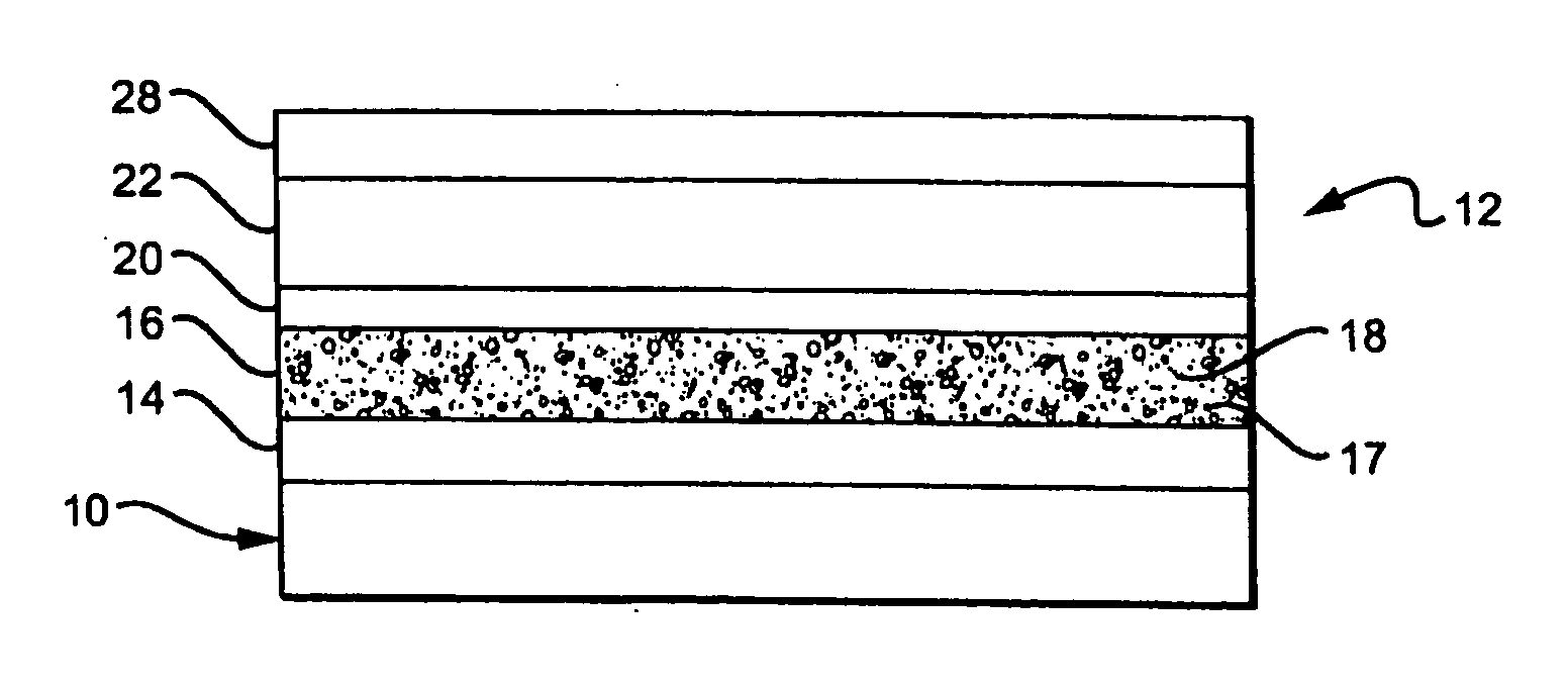
[0013]The present invention is directed to a non-destructive, electrically-activated layered construction providing decontamination to an adjacent surface or enclosed space. The layered structure may include a cathode, an electrolyte layer, an anode and a protective surface layer. The system can be activated on demand, actively decontaminating over an extended period of time, and readily regenerated after activation and depletion. In one embodiment of the invention, activation of the system releases an oxidizing agent effective in deactivating chemically or biologically active agents at or near the surface. In another embodiment, a precursor compound that can be electrically decomposed to release an oxidant is included in the layered structure, preferably in the electrolyte layer. In yet another embodiment of the invention, an enclosed space can be decontaminated in the absence of liquids, particularly aqueous media. In a further embodiment, the precursor compound can release halogen ions which react with various different chemical or biological contaminants that may contact the protective layer, thereby destroying, or devitalizing the contaminants. In yet another embodiment, heating the cell surface prior to electrolysis can facilitate the decontamination of resistant contaminants.

Problems solved by technology

The surfaces of devices, and particularly electronics enclosed within or behind a protecting structure such as a control panel or a enclosing case, are particularly difficult to decontaminate once exposed to contaminating or toxic chemical or biological agents.
The difficulties arise in part from the inability to gain access to the enclosed space and, even where access can be accomplished, from the need to introduce decontaminating agents into small spaces in or behind the devices or components thereof.
The aqueous solvent can also be detrimental to the functionality of the device being decontaminated, causing the electrical components to short circuit and metal components to oxidize (rust).
However, each of these references suffers from one or more of the following disadvantages: the active ingredients are external and must be placed in physical contact with the contaminated surface of the object in order to decontaminate it; the composition or resin is active once applied but can not be activated on demand; the active ingredients are difficult to regenerate if depleted; the systems or coatings used for decontamination are inflexible; the oxidizing agent generated is too acidic or too strong an oxidant to be used in many types of applications (e.g. chlorine or chloride), including the disinfection of electronics and sensitive surfaces such as human skin; the solvents or carriers used to deposit, dissolve, or suspend the active ingredients are detrimental to the functionality of the object or device being treated; the addition of liquid disinfectants requires an additional step in the treatment protocol; the decontaminating surfaces are prone to fouling (i.e. buildup of an overlayer of biological or other types of debris) which leads to a loss of activity; inclusion of active halogens in a dressing is problematic owing to the unstable highly reactive state of the active halogen or halogenated compound; activation of the system is hazardous to the environment or to human health or safety; or the technique requires an enclosed space filled with water or aqueous media, heavy or bulky equipment, or is too costly for remote or application.
Although the latter approach may be effective in some situations, it can also lead to overexposure which can kill human cells.

Method used


Image

  • Multilayer self-decontaminating coatings
  • Multilayer self-decontaminating coatings
  • Multilayer self-decontaminating coatings

Examples


example 1

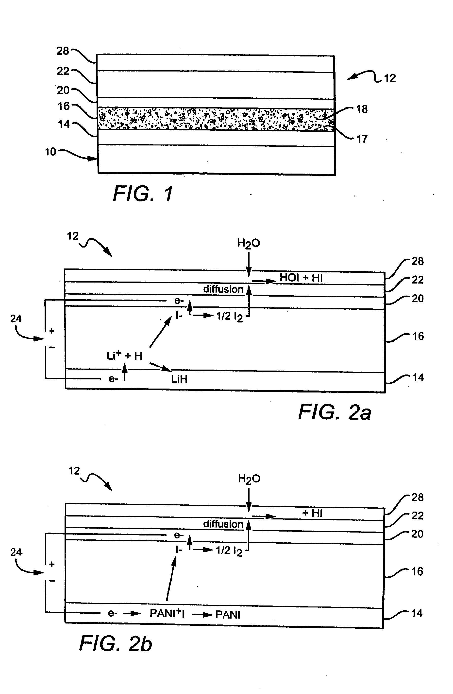
[0071]An experimental cell constructed as in FIG. 2b with PANI iodide cathode, an electrolyte containing EC, PC, PAN, TPAI (34:50:7.77:7.77 by weight), a Teflon fabric separator and a platinized carbon anode was polarized with a positive voltage applied to the anode vs the cathode for five minute intervals.

[0072]Iodine flowing from the coating was detected by exposure to a disk of Watman #44 filter paper which was previously soaked in 0.5 M KI and then dried. A 6 mm diameter disk cut from the paper was placed over the multilayer coating to react with the evolving elemental iodine. The reaction immobilized the evolved I2 vapor as brown KI3 product within the paper through the reaction:

½I2(gas+KI(solid)→KI3(solid)

[0073]Subsequently, the exposed disk containing immobilized elemental iodine developed an intense blue color when placed in a test tube to which was added 2 mL of 1% starch solution (Aldrich 319554). Iodide (I), in contrast, develops no color. The blue color developed by the ...

example 2

[0074]A first example of a layered electrochemical cell uses a cathode 14 containing a combination of Ketjen black (an oil furnace carbon black) and PANT iodide, preferably 21%w Ketjen black and 79%w PANI iodide, and an electrolyte layer 16 comprising a polyacrylonitrile (PAN) gel 17, from about 7 to about 8% tetrapropyl ammonium iodide (TPAI) 18, from about 33 to about 34%w ethylene carbonate (EC), from about 48 to about 50%w of propylene carbonate (PC) and from about 8 to about 12%w of PAN.

[0075]The anode 20 contained platinized carbon with a PVA (Polyvinyl alcohol) binder, platinized woven carbon fabric, or a platinized carbon fiber tissue (obtained from Tech Fiber Products), preferably about 1%w Pt in carbon. The surface covering / membrane 22, 28 was a hydrophobic porous membrane or microporous filter paper, typically coated with a polyurethane or a fluorocarbon formed of Teflon®, Fluorothane™ or Sartech H. As an alternative, a Teflon separator may also be placed between the elec...

example 3

[0076]A second example of the layered electrochemical cell 12 contains:[0077]1) a cathode 14 containing a coating formed from a paste of ground 2,5 dimercapto-1,3,4 thiadiazole, a conducting polymer such as set forth in U.S. Pat. No. 5,665,492, dispersed in a carrier liquid, forming a flowable liquid that is painted on the device, structure or substrate. Alternatively, polyanaline iodide (PANI iodide) can be electrodeposited or otherwise deposited on the surface. As a third alternative, Prussian Blue can be electrodeposited on the substrate or dispersed in a carrier liquid and painted on the surface.[0078]2) The electrolyte layer 16 contains a hydrophobic ionic layer which includes a halide containing compound 18, for example KI or other solid or gel electrolyte containing KI.[0079]3) The anode 20 may be a porous, solid conductor which can be formed from a slurry or dispersion of carbon black, platinized carbon black or Pd metallized TiO2. The anode 20 may also include a photosensit...


PUM

PropertyMeasurementUnit
Flow rateaaaaaaaaaa
Flexibilityaaaaaaaaaa

Abstract

A layered construction for use in decontaminating a surface or enclosed space is described. The construction is an electrochemical cell which includes a cathode, an electrolyte layer, an anode and a protective surface layer. A precursor compound that can be electrically decomposed to release an oxidant, on demand and over an extended period of time, is included in the layered structure, preferably in the electrolyte layer. The oxidant compounds react with various different chemical or biological contaminants in contact the protective layer, thereby deactivating, destroying or devitalizing the contaminants. The layered construction is suitable for application to a device or substrate, or placement in an enclosed space, and can be used on sensitive surfaces such as electronic components and human skin.

Description

CROSS REFERENCE TO RELATED APPLICATION[0001]This application claims priority to the earlier provisional application entitled “MULTILAYER SELF-DECONTAMINATING COATINGS,” Ser. No. 60 / 722,567, filed Sep. 30, 2005, the disclosures of which are hereby incorporated herein by reference.STATEMENT AS TO FEDERALLY SPONSORED RESEARCH[0002]This invention was made with Government support under HR0011-04-C-0131 awarded by the Defense Advanced Research Projects Agency (DARPA). The Government has certain rights in this invention.BACKGROUND[0003]1. Field of the Invention[0004]The present invention relates primarily to a multi-layered electrically activated coating or appliqué applied to devices or substrates, particularly electronic and circuit components which can be automatically activated, or activated at the option of the user, to release an oxidizing agent to decontaminate the surface of the substrate or device while not being destructive of the underlying substrate or the surrounding environme...

Claims


Application Information

Patent Timeline
IPC IPC(8): C25D17/00C25D9/04
CPCA61L2/0011A61L2/0094A61L2/035C02F1/4674A61L2/235A61L2202/26A61L2/20
Inventor KENDIG, MARTIN W.CHUNG, YOUNG J.HARKER, ALAN B.STRAUSS, DENNIS R.ELLIS, WALTHERPOWERS, LINDA S.
Owner TELEDYNE SCI & IMAGING
Learn More