Self-supporting thin polymer film

Inactive Publication Date: 2012-05-10
TOKYO INST OF TECH
View PDF5 Cites 27 Cited by
  • Summary
  • Abstract
  • Description
  • Claims
  • Application Information

AI Technical Summary

Benefits of technology

[0024]According to the present invention, a self-supporting thin polymer membrane having a large s

Problems solved by technology

Though such a method can produce a self-supporting thin membrane, the procedures of the above-mentioned methods are complicated, and the use of these methods may result in aggregates of microcrystal domains.
Thus, the practicability of these methods is not high.
Because of this severe process, it is difficul

Method used


Image

  • Self-supporting thin polymer film
  • Self-supporting thin polymer film
  • Self-supporting thin polymer film

Examples


example 1

[0086]A block copolymer was synthesized as follows.

[0087]A liquid crystalline methacrylic acid ester monomer MA (Stb) was synthesized as follows.

[0088]4-Butylbenzyl alcohol was prepared by reducing 4-butylbenzoic acid (manufactured by Tokyo Chemical Industry Co., Ltd., special grade) by a boron trifluoride diethyl ether complex and sodium borohydride. 4-Hydroxybenzaldehyde (manufactured by Tokyo Chemical Industry Co., Ltd., special grade) and 11-bromo-1-undecanol (manufactured by Wako Pure Chemical Industries, Ltd., special grade) were condensed by a Williamson method to obtain 4-(11-hydroxyundesiloxy)benzaldehyde. The 4-butylbenzyl alcohol prepared above was brominated by hydrogen bromide, followed by a reaction with triphenyl phosphine (manufactured by Wako Pure Chemical Industries, Ltd., special grade) to obtain (4-butylbenzyl)triphenylphosphonium bromide. The resulting phosphonium salt was reacted with potassium t-butoxide to generate an ylide, and the 4-(11-hydroxyundesiloxy)be...

example 2

[0093]A solution of 1% by weight of cellulose acetate (MW: 30,000) in acetone was spin-coated onto a silicon wafer at 3,000 rpm for 60 sec to form a sacrificing layer. The resulting thin film was heated at atmospheric pressure at 60° C. for 1 hour to evaporate the acetone remaining in the thin film. Subsequently, a solution of 4% by weight of the copolymer produced in Example 1 in chloroform was spin-coated onto the sacrificing layer at 2,000 rpm for 30 sec, followed by heating (annealing) in vacuum at 190° C. for 2 hours to obtain a microphase-separated structure membrane.

example 3

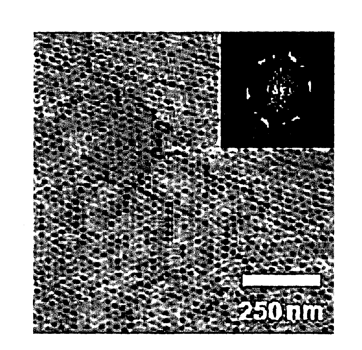
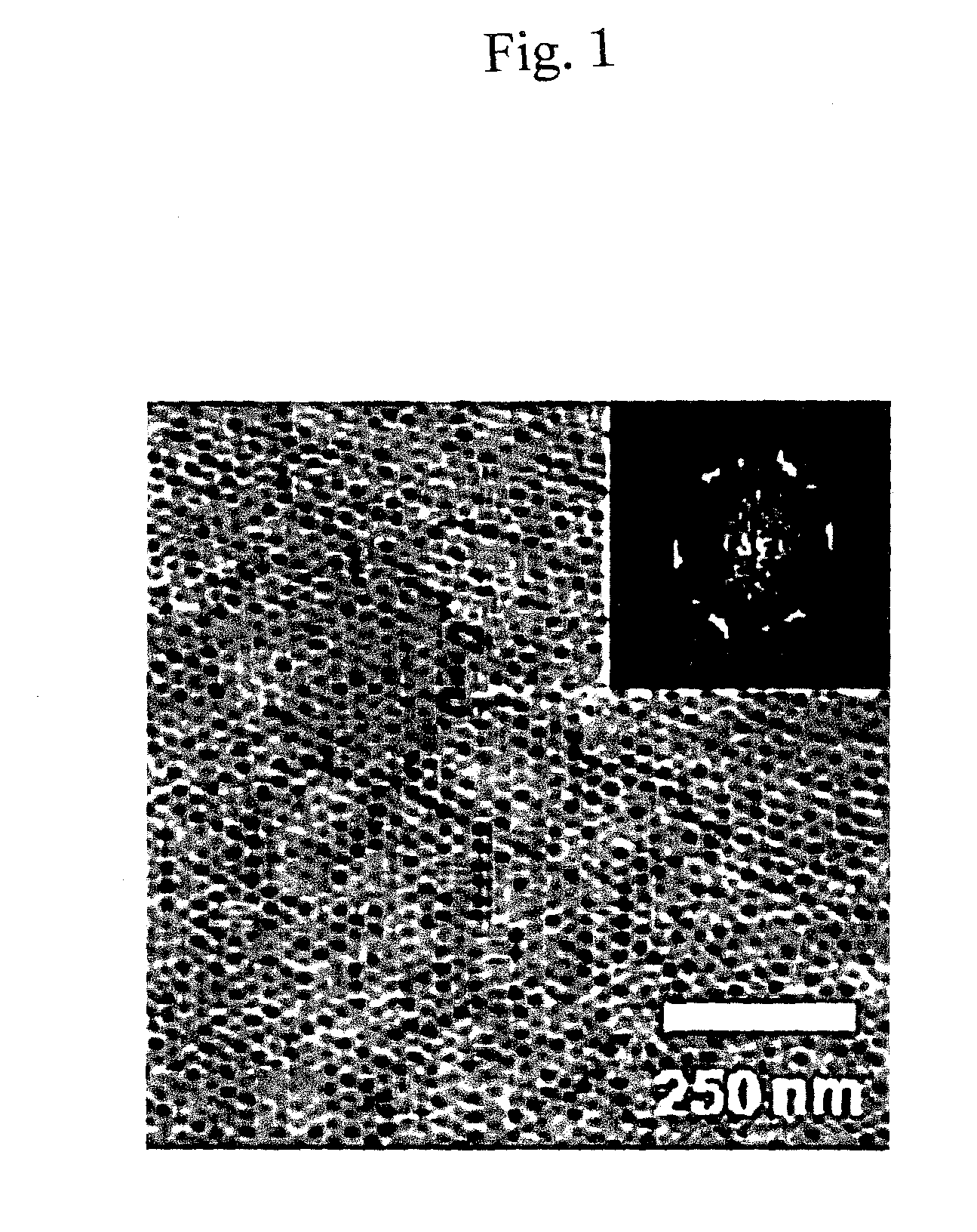
[0094]The microphase-separated structure of the thin polymer membrane prepared in Example 2 was observed for the surface structure by atomic force microscopy (AFM). FIG. 1 is a photograph showing the results of AFM. As obvious from FIG. 1, a hexagonally arrayed dot pattern derived from poly(ethylene oxide) blocks (hydrophilic polymer component) was observed on the surface of the thin polymer membrane prepared in Example 2.

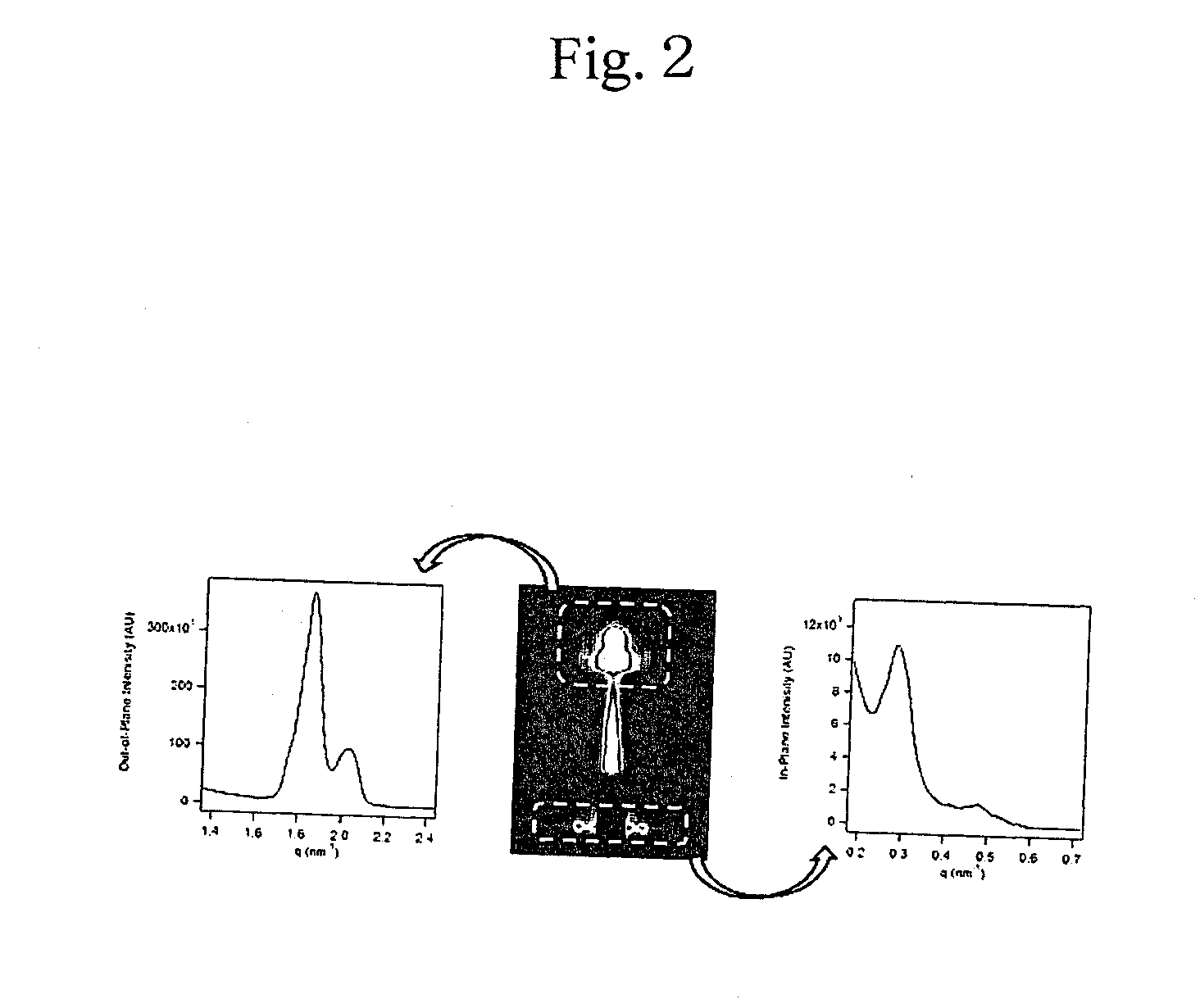
[0095]Then, the thin polymer membrane prepared in Example 2 was measured for structural periodicity by grazing-incidence small-angle X-ray scattering (GI-SAXS). The results are shown in FIG. 2. As obvious from FIG. 2, it was recognized that the poly(ethylene oxide) block (hydrophilic polymer component) cylinders in the thin polymer membrane prepared in Example 2 are hexagonally arrayed. As obvious from the results of the AFM and the GI-SAXS, it was confirmed that the thin polymer membrane prepared in Example 2 forms a microphase-separated structure also on poly(cel...


PUM

PropertyMeasurementUnit
Diameteraaaaaaaaaa
Diameteraaaaaaaaaa
Strengthaaaaaaaaaa

Abstract

[Object] To provide a self-supporting thin polymer membrane having a large surface area, a high strength, and a perpendicularly oriented cylindrical structure, and to provide a method of producing the membrane.
[Solution] The self-supporting thin polymer membrane of the present invention is a self-supporting thin polymer membrane including a block copolymer in which a hydrophilic polymer component and a hydrophobic polymer component having a crosslinkable structure are linked to each other by covalent bonding, and in the self-supporting thin polymer membrane, the hydrophilic polymer component forms unidirectionally oriented cylinders, and the hydrophobic polymer component forms crosslinks. The self-supporting thin polymer membrane of the present invention does not have physical pores but allows a material to selectively permeate the cylindrical portions and can be therefore used as various permeable membranes, ultrafiltration membranes, and nanoreactors.

Description

TECHNICAL FIELD[0001]The present invention relates to a self-supporting thin polymer membrane and a method of producing a self-supporting thin polymer membrane, and more specifically relates to a self-supporting thin polymer membrane having a perpendicularly oriented cylindrical structure and a method of producing the membrane.BACKGROUND ART[0002]In recent years, self-supporting thin membranes having large surface areas and nano-order thicknesses have attracted attention because of their possibilities of application to, for example, permselective membranes, microsensors, and drug-delivery membranes. It has been reported that such a thin membrane can be formed by a layer-by-layer (LbL) deposition method (Non-Patent Literature 1), a Langmuir Blodgett (LB) method (Non-Patent Literature 2), or a spin-coating method (Non-Patent Literature 3). In these methods, a sacrificing layer is disposed on a solid substrate, an objective membrane is produced on the sacrificing layer, and then the sa...

Claims


Application Information

Patent Timeline
IPC IPC(8): C08F220/10B29C59/16
CPCC08F20/26B01D2323/345C08J5/18B01D67/0006B01D69/125B01D71/48B01D71/52B01D71/80B01D2323/00B01D2323/30C08F293/005C08F2220/286C08F220/26C08F2220/302C08F220/286C08F220/302
Inventor IYODA, TOMOKAZUYAMAMOTO, TAKASHIASAOKA, SADAYUKIIZUTANI, TASUKU
Owner TOKYO INST OF TECH
Why Eureka
Try Eureka