Process For Recovering Hydrogen And Carbon Dioxide

a carbon dioxide technology, applied in the field of hydrogen and carbon dioxide recovery, can solve the problems of high capital cost of solvent absorption absorber and stripper column, large carbon dioxide cost of hydrogen production, and large carbon dioxide cost of carbon dioxide capture, etc., to achieve efficient recovery of hydrogen and carbon dioxide, improve process efficiency of hydrogen generation plant, and increase the effect of recoveries

Active Publication Date: 2012-05-17
AIR LIQUIDE LARGE INDS U S LP +1
View PDF0 Cites 39 Cited by
  • Summary
  • Abstract
  • Description
  • Claims
  • Application Information

AI Technical Summary

Benefits of technology

[0008]This present invention provides a method to more efficiently recover hydrogen and carbon dioxide. The present invention further provides the design for carbon dioxide capture from syngas that allows for the simultaneous production of medium to high amounts of hydrogen and the capture of at least 90% of the carbon dioxide in the syngas as a part of the production of hydrogen in a hydrogen generation plant. It is proposed to use combinations of hydrogen selective membranes and carbon dioxide selective membranes together with a carbon dioxide separation unit such that hydrogen and carbon dioxide are produced with increased recoveries and improved process efficiency of the hydrogen generation plant. Increased hydrogen recovery by using hydrogen selective membranes can reduce the size of the reformer, natural gas consumption for feed and fuel etc for the same size hydrogen plant. Increased carbon dioxide recovery will reduce the emissions of carbon dioxide into the atmosphere and will result in cost savings in case of a carbon tax.

Problems solved by technology

However, hydrogen production is associated with large amounts of carbon dioxide (CO2) emissions.
The cost of capture can impact the cost of hydrogen production.
However, the process of solvent absorption requires absorber and stripper columns with very high capital costs.
The regeneration process can involve large amounts of steam or compression energy resulting in high operating costs.
Another disadvantage of using the solvent absorber is that the purity of the recovered carbon dioxide may not be very high and further processing using liquefaction and partial condensation may be needed.
Flue gas processing can pose several challenges because of many new impurities that therefore make the capture process very expensive.
However, carbon dioxide recovery for the unit is not very high.
There is always some hydrogen loss from pressure swing adsorption processes.
In addition, there is some carbon dioxide loss from the capture process which can be recovered by improving the carbon dioxide capture process.

Method used


Image

  • Process For Recovering Hydrogen And Carbon Dioxide
  • Process For Recovering Hydrogen And Carbon Dioxide
  • Process For Recovering Hydrogen And Carbon Dioxide

Examples


Embodiment Construction

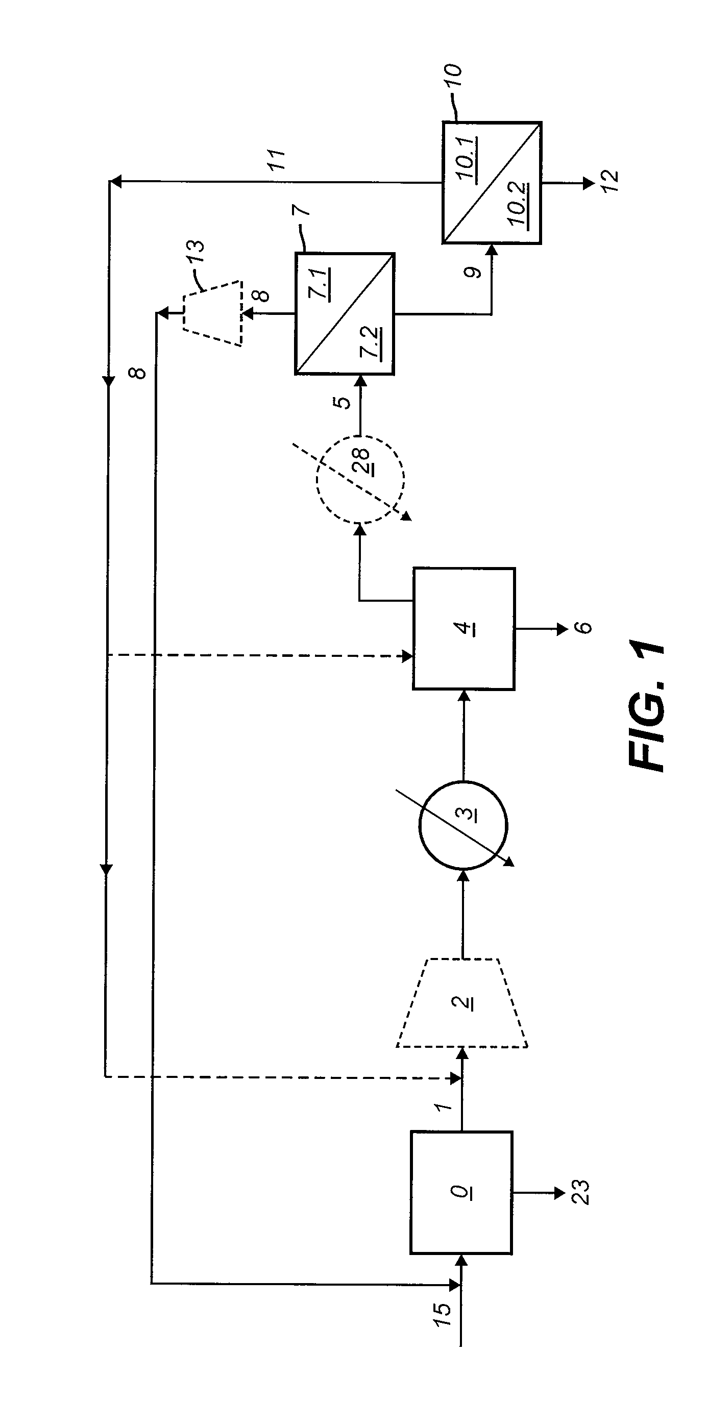
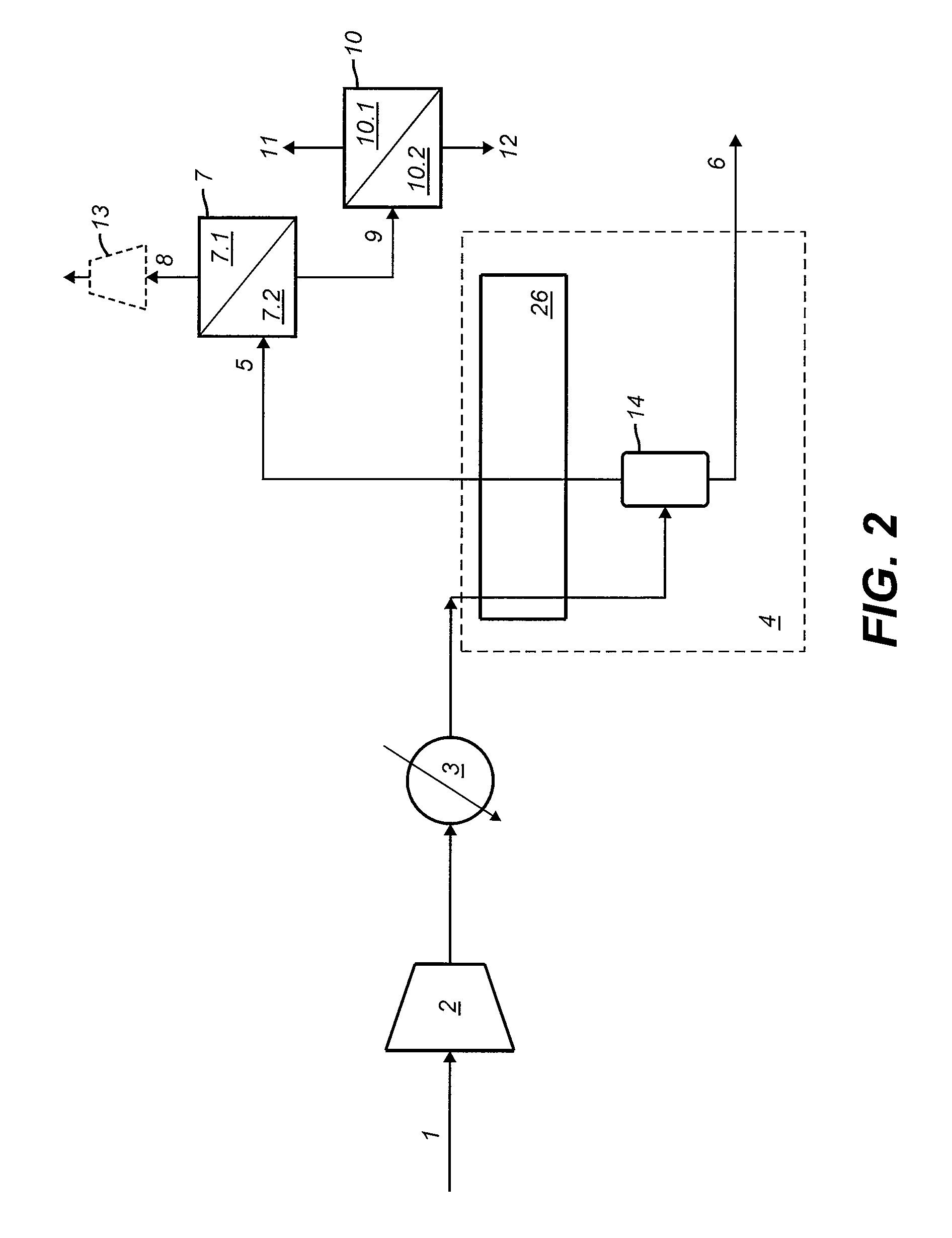
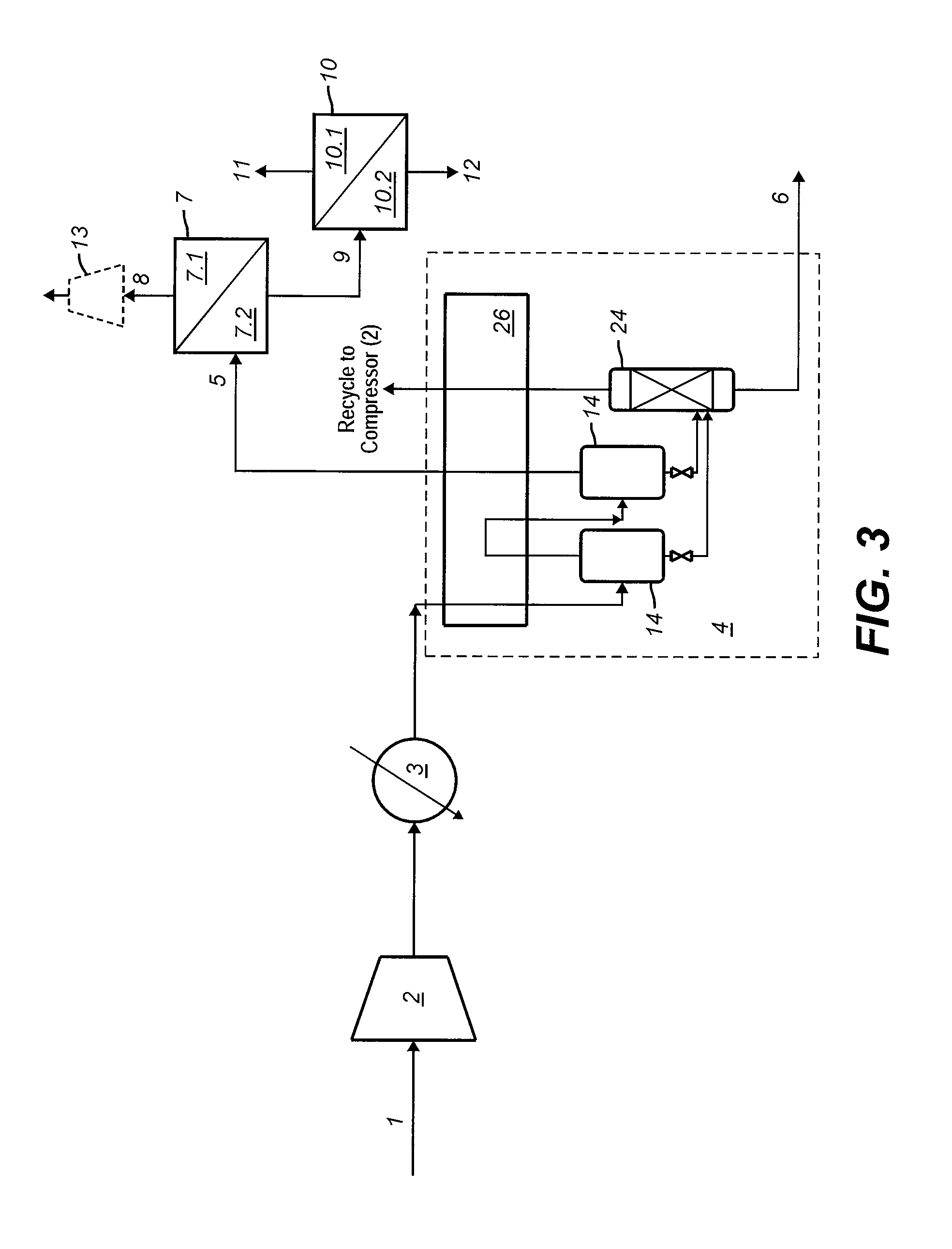
[0014]It is possible to efficiently recover hydrogen and carbon dioxide from process streams obtained from process units which have a purification step that provides a hydrogen rich fraction which can be utilized downstream as in the present process. While overcoming many of the disadvantages of the prior art systems that deal with the recovery of hydrogen and carbon dioxide from such streams, this can be accomplished by integrating a carbon dioxide separation unit, a hydrogen selective membrane separation unit and a carbon dioxide selective membrane separation unit into the process for treating streams taken from such process units in the manner noted herein. In addition, increased production of hydrogen and carbon dioxide capture of equal to or greater than 90% from syngas in hydrogen generation plants may also be accomplished by integrating a carbon dioxide separation unit, a hydrogen selective membrane separation unit and a carbon dioxide selective membrane separation unit into ...


PUM

PropertyMeasurementUnit
pressureaaaaaaaaaa
temperatureaaaaaaaaaa

Abstract

The present invention provides a process for recovering hydrogen and carbon dioxide from a process stream (1) of a process unit (0) wherein the process stream (1) contains at least carbon dioxide, hydrogen and methane. In the process, the process stream (1) is optionally compressing in a first compressor (2) before being cooled in a heat exchanger (3) to a temperature equal to or less than −10° C. Next, the cooled process stream (1) is separated and purified in a carbon dioxide separation unit (4) to produce a carbon dioxide rich liquid stream (6) and a carbon dioxide lean non-condensable stream (5) with the carbon dioxide rich liquid stream (6) being withdrawn as a carbon dioxide product for further use. The carbon dioxide lean non-condensable stream (5) is then withdrawn from the carbon dioxide separation unit (4) and passed through a hydrogen selective membrane separation unit (7) to form a hydrogen rich permeate stream (8) with the remaining components in the carbon dioxide lean non-condensable stream (5) forming a hydrogen lean residue stream (9). The hydrogen lean residue stream (9) is passed through a carbon dioxide selective membrane separation unit (10) to form a carbon dioxide enriched permeate stream (11) with the remaining components in the hydrogen lean residue stream (9) forming a carbon dioxide depleted residue stream (12). The hydrogen rich permeate stream (8) is optionally compressed in a second compressor (13) and recycled for use as a supplemental feed stream in the process unit (0) or in other processes. The carbon dioxide enriched permeate stream (11) is recycled to the process stream (1) prior to the compressor (2) or within the compressor (2) between stages of compression, or to the carbon dioxide separation unit (4) while the carbon dioxide depleted residue stream (12) is withdrawn for further use. The present invention further relates to the use of this process within a hydrogen generation plant to increase recovery of hydrogen and capture equal to or greater than 90% of the carbon dioxide in the syngas stream.

Description

CROSS-REFERENCE TO RELATED APPLICATIONS[0001]This application claims the benefit of U.S. Provisional Application No. 61 / 412,657, filed Nov. 11, 2010, the entire contents of which are incorporated herein by reference.FIELD OF THE INVENTION[0002]The present invention relates to a process for recovering hydrogen and carbon dioxide from a process stream utilizing a carbon dioxide separation unit and two membrane separation units. The present invention further relates to a process for producing hydrogen from a hydrocarbon containing feed gas and capturing at least 90% of the carbon dioxide present in the syngas of a hydrogen generation plant utilizing a carbon dioxide separation unit and two membrane separation units.BACKGROUND[0003]Hydrogen is an important feedstock for many chemical and petrochemical processes. However, hydrogen production is associated with large amounts of carbon dioxide (CO2) emissions. Accordingly, it is desirable to not only provide a means to produce hydrogen but...

Claims


Application Information

Patent Timeline
Patent Type & Authority Applications(United States)
IPC IPC(8): C01B31/20C01B3/02C01B32/50
CPCB01D53/002Y02C10/12B01D2257/108B01D2257/504C01B3/501C01B3/506C01B2203/0233C01B2203/0283C01B2203/0405C01B2203/046C01B2203/0475C01B2203/142F25J3/0223F25J3/0252F25J3/0266F25J3/0625F25J3/0655F25J3/067F25J2200/02F25J2205/04F25J2205/40F25J2205/60F25J2205/80F25J2215/04F25J2220/82F25J2230/30F25J2245/02F25J2270/90Y02C10/10B01D53/226Y02C20/40Y02P30/00Y02P20/151
Inventor TERRIEN, PAULCHAUBEY, TRAPTISHANBHAG, PURUSHOTTAM V.GROVER, BHADRA S.VAUK, DENNIS A.DARDE, ARTHUR
Owner AIR LIQUIDE LARGE INDS U S LP
Why Eureka
Try Eureka