Silicate-free developer compositions

a developer composition and silicate-free technology, applied in the field of silicate-free and sugar-free alkaline developer compositions, can solve the problems of increasing the cost of imaging equipment, reducing the cleaning reducing the efficiency of processing equipment, so as to achieve the effect of inhibiting dissolution and simplifying the cleaning of processing equipmen

Inactive Publication Date: 2012-05-24
EASTMAN KODAK CO
View PDF6 Cites 8 Cited by
  • Summary
  • Abstract
  • Description
  • Claims
  • Application Information

AI Technical Summary

Benefits of technology

[0044]The developer compositions can be used as an aqueous alkaline developer to process imaged positive-working lithographic printing plate precursors. The developers compositions are free of silicates and metasilicates and free of sugars (for example, non-reducing sugars), meaning that none of these compounds are purposely added or incorporated by any means into the developer compositions. Although silicates are effective inhibitors for inhibiting dissolution of aluminum oxide in such developers, the presence of a silicate in a developer composition causes precipitation of water-insoluble aluminosilicates that contaminate the processing bath and complicates the cleaning of the processing apparatus.
[0045]While the presence of the noted metal ions present in the developer composition serves as extremely effective inhibitors for the non-imaged areas of the positive-working lithographic printing plate precursors, the so-called “sharpening” effect was recognized as an additional problem to be solved. We found that this problem can be reduced by the presence of a suitable alkali metal salt as defined herein such as citric acid (or in the form of a citrate) in the developer composition.

Problems solved by technology

These lithographic plate precursors typically require a relatively high amount of energy input and thereby have limited productivity when the available infrared laser power is limited.
Another drawback of ablative lithographic printing plate precursors is the need to remove debris during imaging, adding to the cost of the imaging equipment and more noise during the operation of such equipment.
These lithographic printing plate precursors typically have limited durability on press and limited resistance to press chemicals, unless such plates are baked at high temperature after image development.
The baking step adds to equipment cost and energy consumption.
Various attempts have been made to improve the run length on press and chemical resistance of the no-preheat plates, but each attempt has one or more limitations.
For example, no-preheat lithographic printing plate precursors containing some acrylic binders, described in U.S. Pat. No. 6,143,464 (Kawauchi) typically suffer from inadequate differentiation in the solubility in alkaline developers between the IR laser exposed areas and non-exposed areas and from such problems like poor scratch resistance.
This inadequate image differentiation often leads to excessive coating loss in the non-IR exposed areas or incomplete removal of the coatings from the IR exposed areas.
One cause of short development cycle and excessive difficulty in cleaning the automatic processor relates to partial dissolution of aluminum oxide film on the substrates of typical lithographic printing plate precursors in the developer solution.
However, the use of silicate salts itself adds to the dirtiness of the processor bath.
It was found that developers containing lithium chloride are very slow in dissolving the infrared laser exposed coating containing polyvinyl acetal that also has hydroxyaryl ester groups and therefore are considered unsuitable for processing such precursors.
During a processing cycle, when the developer is “loaded” with dissolved coating materials, a problem known as “sharpening” become evident.
“Sharpening” occurs when the developing composition becomes more aggressive in its developing activity so that the non-exposed regions in the imageable layer are attacked by the developer composition, resulting in increased printing plate weight loss and decreased dot size (“dot sharpening”) in the resulting printed imaged.

Method used


Image

  • Silicate-free developer compositions
  • Silicate-free developer compositions
  • Silicate-free developer compositions

Examples


invention example 1

[0223]A sample of Precursor 1 was exposed using the Kodak® Magnus 400 Quantum imager at a range of energies, 50 mJ / cm2 to 200 mJ / cm2 and processed in a Mercury Mark VI processor using Developer 1 (shown below) at 23° C. for 20 seconds.

Developer 1ComponentConcentration %KOH2.70Potassium citrate1.75Bayhibit ® AM0.50CaCl2 × 2H2O0.04DowFax ® 2A10.50Hydromax 3000.10Water94.4

[0224]The results are shown in the following table.

Corrosion, WeightClearing PointLinearity Pointloss (Δm / S, g / m2)CDL %(mJ / cm2)(mJ / cm2)0.020.85090

[0225]Clearing Point is the lowest imaging energy at which the exposed regions were completely removed by the developer at a given temperature and time. Linearity Point is the energy at which the 50% dots at 200 lpi screen are reproduced as 50%±0.2% dots). Cyan Density Loss (CDL %) provides a measure of the resistance of the non-exposed regions on the lithographic printing plate to the developer. CDL % is calculated using the following formula.

CDL%=(ODb−ODa) / ODb×100

wherein O...

invention example 2

[0230]Invention Example 1 was repeated using samples of Precursor 2. The results obtained using fresh Developer 1 through an automatic processor are summarized in the following table.

Corrosion, WeightClearing PointLinearity Pointloss (Δm / S, g / m2)CDL %(mJ / cm2)(mJ / cm2)0.020.560100

[0231]In a loading test, a sample of Precursor 2 was imaged in the same way as in Invention Example 1 and was developed by hand using samples of Samples of Developer 1 that had been loaded with coating ingredients contained in the imageable layer of Precursor 1 in amounts corresponding to loading levels of 1.5 m2 / l, 3 m2 / l, 4.5 m2 / l, 6 m2 / l, and 9 m2 / l. The samples of Developer 1 were tested at 23° C. and 25 seconds dwell time. The following table shows the results of these tests.

Plate Loading Level(m2 / liter)CDL (%)Dot 50% (100 mJ / cm2)00.949.61.50.749.53.01.149.86.01.050.39.01.050.6

[0232]These results show that the image quality in terms of CDL and 50% dot readings using Precursor 2 is stable after Developer ...

invention example 3

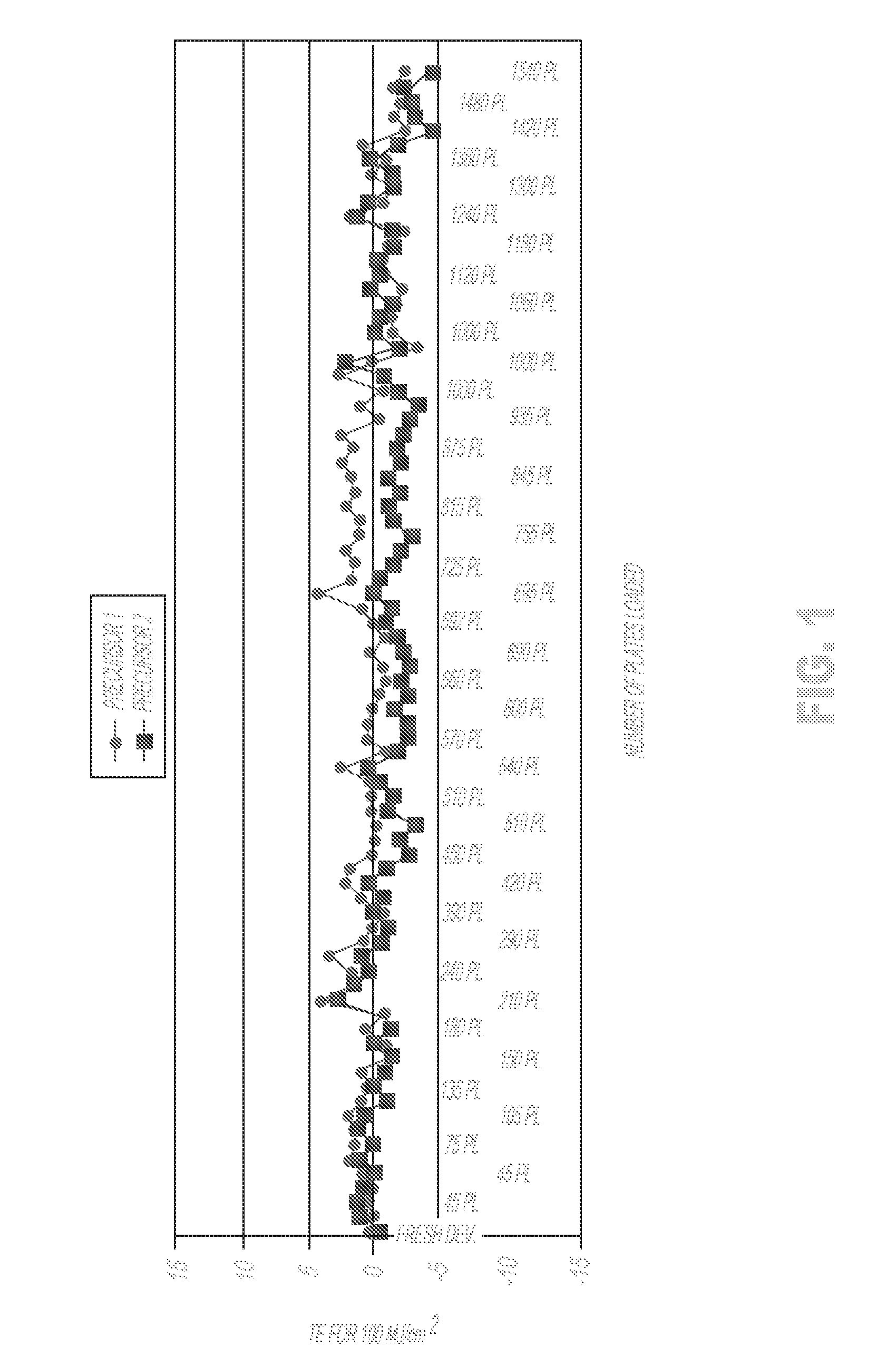
[0233]This example illustrates a process for maintaining the stability of Developer 1 in a Kodak Mercury Marc VI Processor during a loading cycle using 1030 cm×800 cm samples of Precursor 1 with its entire imageable layer imaged using a Kodak® Magnus 400 Quantum imaging device at 100 mJ / cm2 and using 1030 cm×800 cm samples of Precursors 1 and 2 imaged on the same imaging device with patterns containing areas representing 1% dots up to 99% dots at 200 LPI for image quality evaluation. The processor was set at a printing plate transport speed of 1500 mm / min (20 seconds dwell time) except that when test samples of Precursor 2 were processed, the transport speed was adjusted to 1700 mm / min (17 seconds dwell time). The developer tank temperature was set at 23° C. at all times and Developer 1 was replenished with Replenisher 1 at a rate of 40 ml / m2 of processed plates and 1 liter was added every 24 hours. The composition of Replenisher 1 is described in the following table.

Replenisher 1Co...


PUM

PropertyMeasurementUnit
mol %aaaaaaaaaa
mol %aaaaaaaaaa
mol %aaaaaaaaaa

Abstract

A silicate-free alkaline aqueous developer composition has a pH of at least 12 and comprises a hydroxide alkali agent, a metal cation M2+ selected from barium, calcium, strontium, and zinc cations, a chelating agent for the metal cation, and an alkali metal salt that is different than the other components. These developer compositions can be used to process imaged positive-working lithographic printing plate precursors to prepare lithographic printing plates.

Description

FIELD OF THE INVENTION[0001]This invention relates to silicate-free and sugar-free, alkaline developer compositions that are useful to process imaged positive-working lithographic printing plate precursors such as those that have imageable layers containing vinyl acetal recurring units. This invention also relates to methods of using the developer compositions of this invention and to kits comprising a developer composition and one or more precursors.BACKGROUND OF THE INVENTION[0002]In conventional or “wet” lithographic printing, ink receptive regions, known as image areas, are generated on a hydrophilic surface. When the surface is moistened with water and lithographic printing ink is applied, the hydrophilic regions retain the water and repel the ink, and the ink receptive regions accept the ink and repel the water. The ink is eventually transferred to the surface of a material upon which the image is to be reproduced.[0003]Lithographic printing precursors useful for preparing lit...

Claims


Application Information

Patent Timeline
Patent Type & Authority Applications(United States)
IPC IPC(8): G03G9/16G03F7/004G03F7/20
CPCB41C1/1008B41C2210/02B41C2210/24G03F7/327B41C2210/06G03F7/322
Inventor LEVANON, MOSHEASKADSKY, LEONID
Owner EASTMAN KODAK CO
Why Eureka
Try Eureka