Frequency comb source with large comb spacing

a comb source and frequency technology, applied in the direction of optical radiation measurement, instruments, spectrometry/spectrophotometry/monochromators, etc., can solve the problems of difficult mass production of fiber comb sources with large comb spacing, difficult generation of broad frequency spectra with widely spaced comb lines, and difficulty in developing practical comb sources for use in the mid-ir spectral region, etc., to achieve low carrier phase noise, easy adjustment of dispersion compensation elements

Inactive Publication Date: 2012-05-31
IMRA AMERICA
View PDF2 Cites 47 Cited by
  • Summary
  • Abstract
  • Description
  • Claims
  • Application Information

AI Technical Summary

Benefits of technology

[0013]At least one embodiment includes a mode locked waveguide comb laser having a compact dispersion control unit (DCU) in the laser cavity. The DCU may be capable of producing net GVD in a range from a positive value to a negative value, and preferably provides continuous adjustment of dispersion. In various implementations a DCU may provide much lower loss than achievable with dispersion compensators based on fiber Bragg gratings.
[0014]In various embodiments, the use of a single angularly dispersive optical element provides a very compact and easily adjustable dispersion compensation element. The dispersive element can be incorporated into a mode locked waveguide cavity, allowing for

Problems solved by technology

Notwithstanding numerous practical advances in fiber comb technology, fiber comb sources with large comb spacing are still difficult to manufacture and not readily applicable to mass production.
Moreo

Method used


Image

  • Frequency comb source with large comb spacing
  • Frequency comb source with large comb spacing
  • Frequency comb source with large comb spacing

Examples


Embodiment Construction

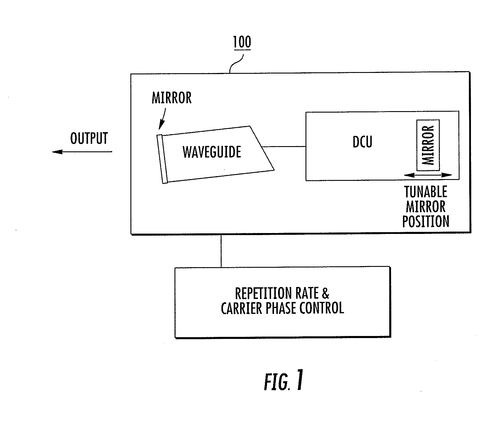
[0032]FIG. 1 represents an exemplary embodiment of a repetition rate tunable waveguide laser 100 with large comb spacing for use in a waveguide laser system. Tunable waveguide 100 laser may also include both repetition rate and carrier phase control, and a dispersion control unit (DCU). In this example, a Fabry-Perot cavity design with two cavity mirrors is shown, where the first cavity mirror (right side) is mounted on a piezoelectric transducer allowing for piston type of control. The other cavity mirror (left side) is used for output coupling, and in this example is adjoined to the waveguide. The first cavity mirror is also part of the dispersion control unit, which allows for setting of the overall cavity group velocity dispersion, where the overall cavity group velocity dispersion can preferably be set continuously from negative to positive values. Carrier phase can be controlled, for example, by controlling the optical pump power to the waveguide laser. An optical pump can be ...


PUM


Abstract

A frequency comb laser providing large comb spacing is disclosed. At least one embodiment includes a mode locked waveguide laser system. The mode locked waveguide laser includes a laser cavity having a waveguide, and a dispersion control unit (DCU) in the cavity. The DCU imparts an angular dispersion, group-velocity dispersion (GVD) and a spatial chirp to a beam propagating in the cavity. The DCU is capable of producing net GVD in a range from a positive value to a negative value. In some embodiments a tunable fiber frequency comb system configured as an optical frequency synthesizer is provided. In at least one embodiment a low phase noise micro-wave source may be implemented with a fiber comb laser having a comb spacing greater than about 1 GHz. The laser system is suitable for mass-producible fiber comb sources with large comb spacing and low noise. Applications include high-resolution spectroscopy.

Description

CROSS-REFERENCE TO RELATED APPLICATION[0001]This application is related to U.S. patent application Ser. No. 12 / 895,127, filed Sep. 30, 2010, and entitled “Optical signal processing with modelocked lasers”.[0002]This application is related to U.S. patent application Ser. No. 12 / 630,550, filed Dec. 3, 2009, and entitled “Highly rare-earth-doped optical fibers for fiber lasers and amplifiers”.[0003]This application is related to U.S. patent application Ser. No. 12 / 399,435, filed Mar. 6, 2009, and entitled “Optical scanning and imaging systems based on dual pulsed laser systems”.[0004]This application is related to U.S. patent application Ser. No. 11 / 546,998, filed Oct. 13, 2006, and entitled “Laser based frequency standards and their application”, now U.S. Pat. No. 7,809,222.[0005]This application is related to U.S. patent application Ser. No. 11 / 372,859, filed Mar. 10, 2006, and entitled “Pulsed laser sources”, now U.S. Pat. No. 7,649,915.[0006]The disclosures of application Ser. Nos....

Claims


Application Information

Patent Timeline
IPC IPC(8): G01J3/00H01S3/10H01S3/098
CPCG01J3/10H01S3/0675H01S3/08054H01S3/0809H01S3/1106H01S3/105H01S3/1118H01S3/1618H01S3/10046G02F1/365G02F1/3528H01S3/0085H01S3/0092H01S3/1112H01S3/1115
Inventor FERMANN, MARTINHARTL, INGMAR
Owner IMRA AMERICA
Why Eureka
Try Eureka