Process for continuous dry conveying of carbonaceous materials subject to partial oxidization to a pressurized gasification reactor

Inactive Publication Date: 2012-07-19
BAIRAMIJAMAL FARAMARZ
View PDF11 Cites 16 Cited by
  • Summary
  • Abstract
  • Description
  • Claims
  • Application Information

AI Technical Summary

Benefits of technology

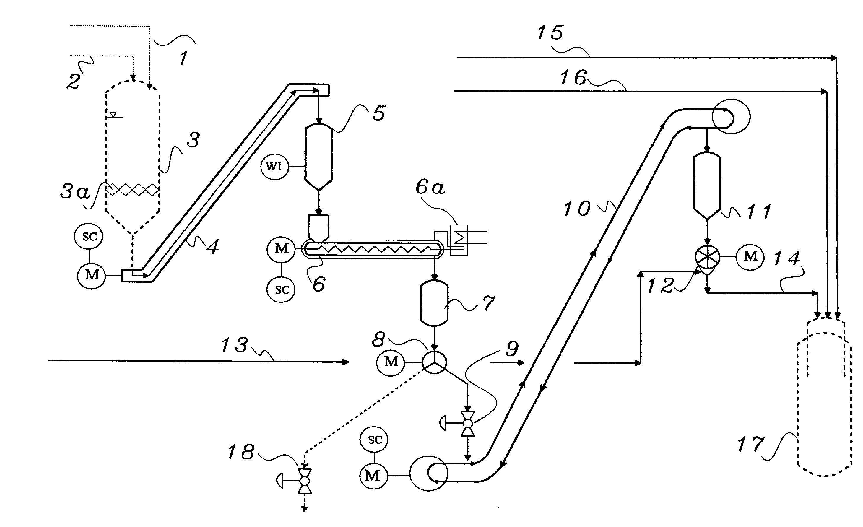
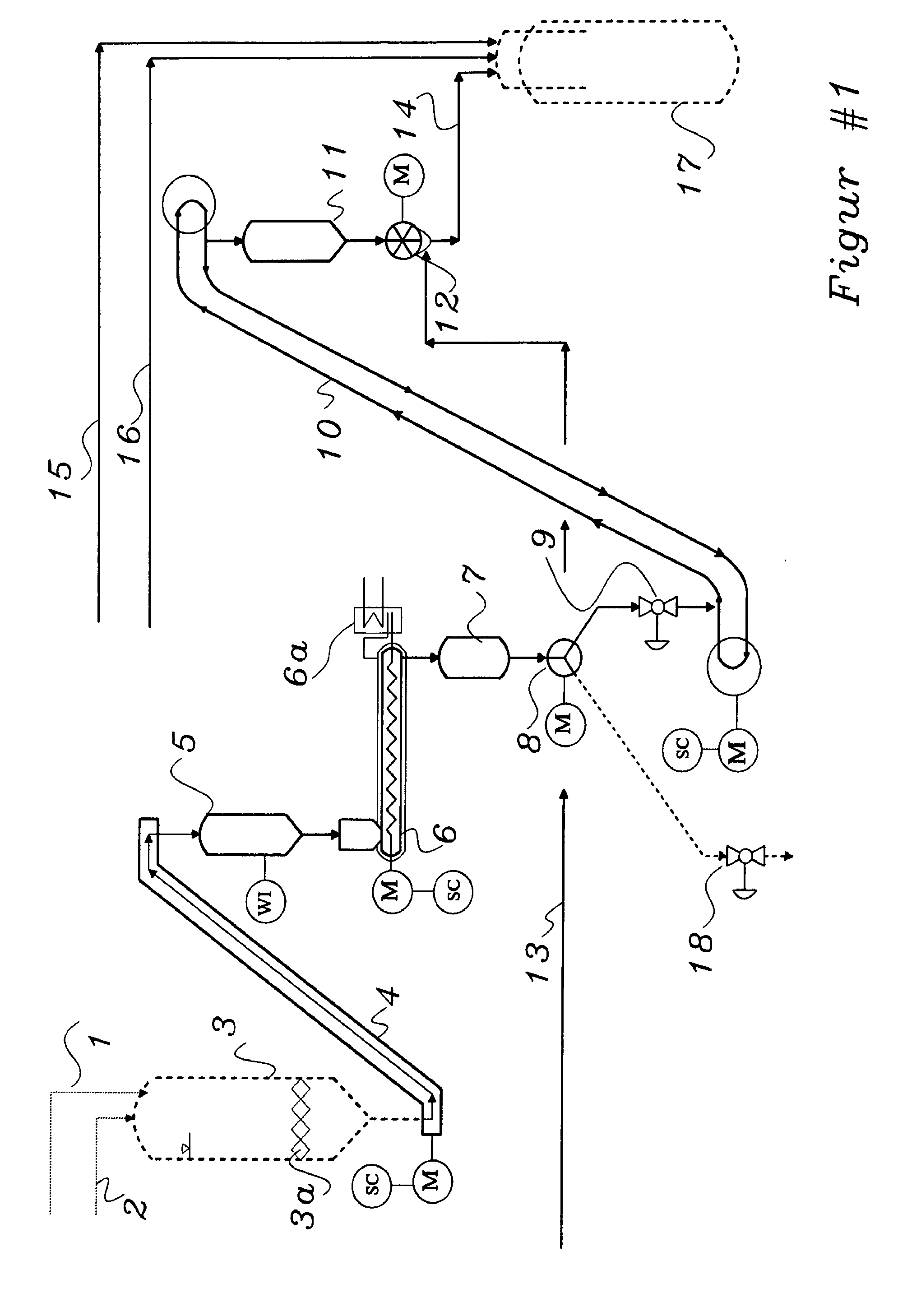
[0047]In further advantage the process shall be carried out in a way that the accruing friction heat of bulk solid can be diverted from the feed material along the compression zone of extruder indirectly through cooling circuit by application of cooling circuit water, coolant media or refrigerating coolant, exchanged over the jacket cooling coils of extruder and / or optionally through the cooling extruder shaft. The cooling procedure is to be executed in a manner that the carbonaceous material can be kept within a margin of temperature between 20° C. and maximal 100° C., so no partial evaporation of residual volatile compounds and moisture takes place while extruder is densifying the carbonaceous material.
[0061]In added advantage, the low pressure coal hopper deigned for intermediary storage of carbonaceous bulk powdered material is preferably equipped with such suitable discharge device (i.e. implemented oscillomator) for continuous dry transportation of feeding material so that any utilization of gaseous media supposed for upholding the bulk solid under steady movement (moving bed or fluidization bed) is not necessary anymore.
[0063]The invention considers the application of an extruder with two telltale characteristics. The extruder(s) is designated with indirect cooling jacket where the coolant media circulates for deflection of accruing heat as a result of friction along the compression zone. The implemented cooling can include also the indirect cooling of extruder shaft as well. By this measure any undesired evaporation of volatile or moisture compounds constituent in the feeding material can be avoided along the way of compression duly. By this measure all moisture / volatile compound will remain absorbed within the body of feeding material without causing the cavitations effect in the extrusion stage. The second characteristic feature of the extruder employed in the present invention relates to a nibbler, preferably integrated in the body of extruder at the end of compression zone or flanged on outlet nozzle of extruder upstream of the first pressurized vessel. The nibbler crumbles and re-powders the clumped and agglomerated material which grants the flowability of carbonaceous material after the densification stage without disturbing jam-up or plugging in the sequel downstream equipment.

Problems solved by technology

While the pressure elevation of gaseous precursors can be readily carried out by the way of compressor or the pressurization of liquid feed materials via pump, the pressure elevation of dry bulk solid materials arouse serious technical troubles for transformation of precursor to the reactor by actual state-of-the-art method.
The most disadvantage of water as carrier media relates to the considerably reduction of thermal reactor performance.
The combustion reaction leads inevitably to lower reactor yield associated with the fed carbon mass flow due the formation of undesirable CO2 in lieu of intended CO formation.
Thus lock hopper tact time is to be short, that leads to an unduly large size of hoppers and related equipment causing higher investment cost under intermittently operation.
This condition increases the costs in an added measure as well.
Another significant disadvantage of this process is hallmarked with a great number of remote controlled valves operating in OPEN / CLOSE positions pertaining to the actual tact.
That marks the entire process as failure prone and requires adequate process control personnel maintaining the entire equipments above.
Surprisingly, due lack of technically alternative process, there are facilitated a lot of commercial plants employing that process in the commercial plants up to actual time.
In added disadvantage, as a result from the large size of equipment necessary for the handling of precursor in large size silos, there is imperative to provide a carrier gas keeping coal in steady move and fluidization in the hoppers.
But, in turn, the lower μ ratio, the higher roars the extent of adverse technical and economic investment cost impact taking place in the reactor, all reactor downstream plant islands and equipment including the utility fluidizing and conveying gas equipment i.e. compressor, intercoolers and the size of gas buffer tanks too.
The sub-sequel adverse impact for the investment costs by low μ ration skyrockets in particular the footprint of Acid Gas Removal Unit, if the plant is supposed to produce SNG (Substituted Natural Gas) by availing CO2 as fluidizing and conveying carrier gas.
The compressor requires apparently high energy consumption and maintenance.
Usually the inert gas compressor can not be installed redundantly because of high investment and maintenance.
The trip of inert gas compressor leads inevitably to a outage of entire plant.
The much complicated process involving great number of equipment can unfortunately perform ultimately a final outlet pressure of maximum 5 bar suitable for biomass gasification only.
Higher outlet pressure can not be performed by the way of crew conveyor impinged with gaseous N2 or CO2 media.
Other gasifiers employing in large scale plant and operating at high pressure (usually over 40 to 100 bar) can not be addressed by that process beside of other difficulties in sealing and contentment of applicable standards for handling of hazardous bulk solid and gaseous process media.
The DE 10 2008 012 156 A1 (registered on Mar. 1, 2008) admits several problem with screw conveyor but also indicates that a screw conveyor is not able to perform pressurization of feeding material required for commercial gasification plant.
In pursuant to this and also the aforementioned patent applications, the great dangerous case encountering with reflux of hazardous gaseous media from reactor (very toxic CO and explosive H2) could not be solved by directly connected screw conveyor to the reactor.
The pressurized clumpy biomass or coal material can not provide the safe operation of the suggested isolated gate valve in case of jam-up of feeding material or in case of emergency shut-down of plant.
These serious troubles have led to the conclusion, that in all commercial gasification plant the intricate lock hopper system are installed or are planned to be installed in future plants.

Method used


Image

  • Process for continuous dry conveying of carbonaceous materials subject to partial oxidization to a pressurized gasification reactor
  • Process for continuous dry conveying of carbonaceous materials subject to partial oxidization to a pressurized gasification reactor
  • Process for continuous dry conveying of carbonaceous materials subject to partial oxidization to a pressurized gasification reactor

Examples


Embodiment Construction

with Optionally Respect to Redundancy

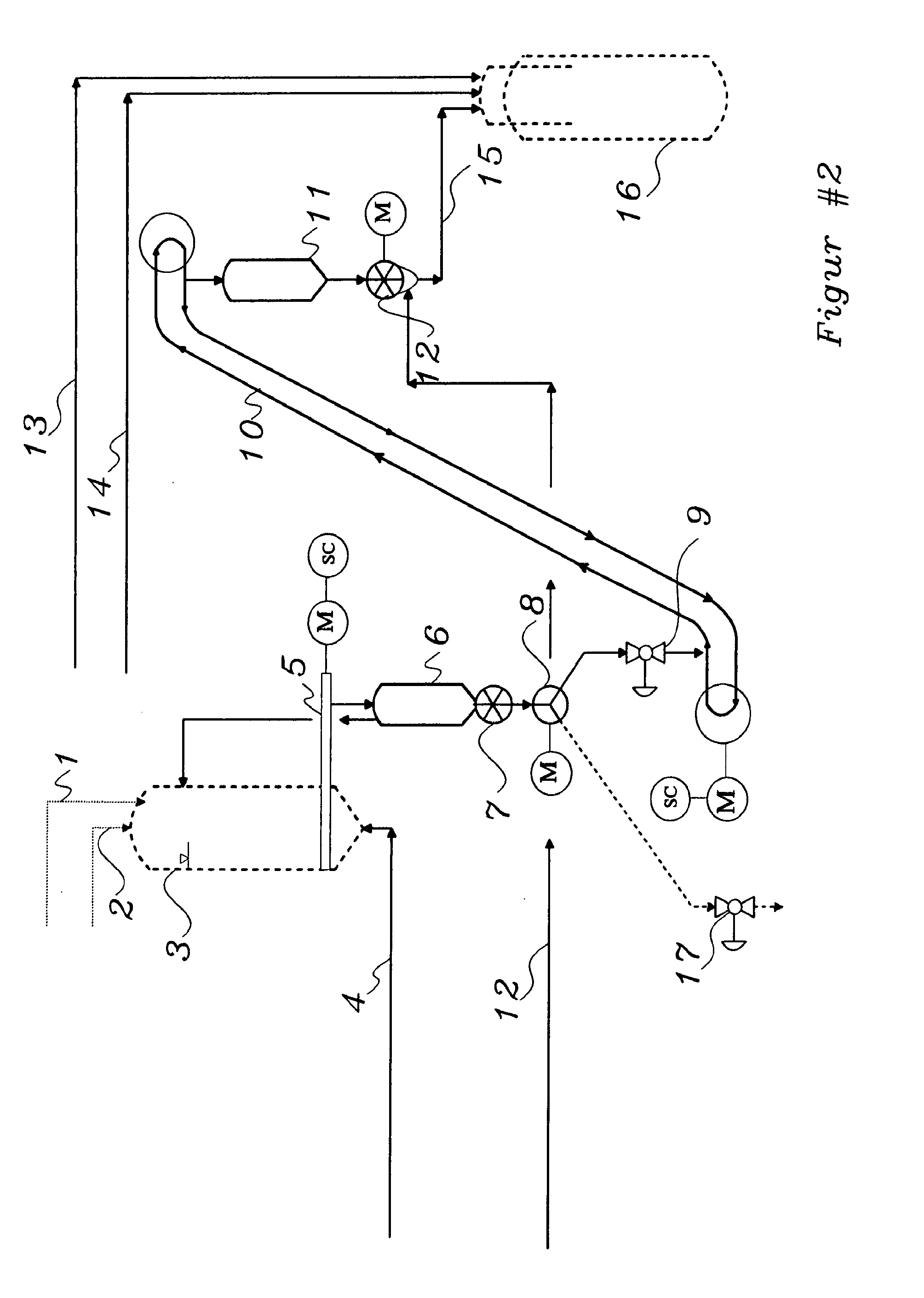
[0087]In light of start up of the plant feeding island as well the aforementioned redundancy, the FIG. 3 might illustrate the process inventively by following exemplary description.

[0088]The preparation and control of requisitions measure prior to ramp up the plant will be checked and permits the start up via IPCS. The system downstream of First Pressurized Vessel (or in case of operation without HP tubular drag conveyor, the Second Pressurized Vessel) is pressurized up to the operation pressure of feeding system, preferably with inert gas or any other appropriate gaseous media i.e. CO2, else. The slam shut valves / shut off valve 9, FIG. 1, 2 or 6f in FIG. 3 are set in CLOSED position. The availability of boundary system (i.e. minimal coal level in LP hopper, cushion gas pressure, lubrication sealing gas pressure, cooling circuit, etc.) releases the plant operability prior to start-up introduction. The isolation valve(s) between HP Discharge Vesse...


PUM


Abstract

The present invention demonstrates a continuous process for dry conveying of powdered coal either a blend of carbonaceous material subject to partial oxidization whereby the conveying feed will be transferred via a suitable conveyer from an atmospheric silo to a or a number of extruder's LP Feeder Vessel and be fed over extruder's inlet chute in continuo to a or a number of extruder(s), in which the dry feed material will be densificated along the compression zone of that extruder up to high pressure and will be discharged over outlet chute into a downstream said First Pressurized Vessel, wherefrom the feeding precursor will be transported via a or a number of in series pressurized tubular-drag conveyor to the said Second Pressurized Vessel, which is equipped with one or more Reactor Feeding Unit(s), referred to Splitter(s), each one consisting of a Star Valve, Reactor-Feed-Line and a said Injection-Line for pneumatic conveying individually, whereby the feed carbonaceous material will be exposed to with injection gaseous media (saturated steam, superheated steam, inter gases, natural gas, N2, CO2, purge gas from synthesis section of ammonia, methanol plant, purge gas from PSA of hydrogen purification section, hydrogen or a blend of those gaseous media in any composition) by the formation of any pneumatic bulk conveying mechanism into a downstream pressurized reactor, preferably a gasification reactor, wherein the transported precursor will be converted chemically under high temperature and elevated pressure via partial oxidization reactions to process gas, slag and ash.

Description

CROSS-REFERENCE TO RELATED APPLICATION[0001]The present application is related in general subject matter to European Patent Application EP 09 012 157.5 filed on Sep. 24, 2009 entitled “Process for continuous dry conveying of carbonaceous materials subject to partial oxidization to a pressurized gasification reactor”.FIELD OF THE INVENTION[0002]The present invention relates to a process for conveying of precursors material for partial oxidization in pressurized reactor, in particular to gasification reactor. The present invention relates also to a device invention pertaining to high pressure bulk solid densification device.[0003]The obtained row process gas from gasification reactor through chemical partial oxidization can be prepared in sequel either for various chemical syntheses or be applied for power generation by use of gas turbine. The processing with the gas turbine opens both the most attractive way for CO2 sequestration and also environmentally benign power generation compa...

Claims


Application Information

Patent Timeline
IPC IPC(8): B01F15/02B01F15/04B01F15/06
CPCC10J3/30C10J2300/0903C10J2200/158
Inventor BAIRAMIJAMAL, FARAMARZ
Owner BAIRAMIJAMAL FARAMARZ
Why Eureka
Try Eureka