Dual Independent Transport Systems For IR Conveyor Furnaces and Methods of Firing Thin Work Pieces

a conveyor furnace and independent transportation technology, applied in conveyors, furnaces, lighting and heating apparatuses, etc., can solve the problems of reducing throughput, abrasion and contamination of back contact layer paste, and large footprint of conventional furnaces, so as to achieve faster processing of wafers, eliminate contamination sources, and improve energy efficiency

Inactive Publication Date: 2012-07-26
TP SOLAR OF USA
View PDF6 Cites 25 Cited by
  • Summary
  • Abstract
  • Description
  • Claims
  • Application Information

AI Technical Summary

Benefits of technology

[0035]In the case of diffusion furnaces where metal mesh belts currently are not used due to contamination of the wafers by the metal belts in contact with the underside of the wafers, the inventive carrier wire wing or “flying bridge” belts may be fitted with small ceramic tubes slipped over the inclined segments. The edges of the wafers contact the ceramic tubes rather than the wire of the incline, thereby eliminating a source of contamination. In still another embodiment, the inclined segments may be coated with glass, of the type formulated to bond with metal, such as radio tube glass. In the alternative, the inclined segments may be coated with a formulation of powdered glass or ceramic plus a binder, and then fired to form a glass or ceramic frit-type coating. It will be evident to one skilled in this art that a wide range of wing and flying bridge designs may be employed while keeping within the scope of the principles of this invention.
[0036]In an important alternative, massless, shadowless finger drive systems may be used in each lane. Such drives comprise spaced-apart chains, preferably roller-link chains having single or double fingers mounted in the hollow chain pivot tubes, which fingers project toward each other. The finger chains are spaced apart just enough so that wafers are carried along the processing path only by point contact of the finger wires with a bottom side edge of the wafers. This drive system is shadowless, in that it eliminates the need for quartz sliders or tubes which are used in the case of wire mesh belts, is more energy efficient and permits faster processing of wafers as more radiant energy is delivered to both sides of the wafers simultaneously. Indeed, rates of travel of wafers transported on finger drives approach or exceed 500″ per minute, permitting dwell time in transiting a peak firing zone on the order of 1 second or less, which is in the range of from about 2× to 10× faster than currently available furnaces.

Problems solved by technology

With respect to adding furnaces, conventional furnaces have a large footprint.
In addition, the contact of the back side of the wafer with the many wires of the conveyor belt contributes to abrasion and contamination of the back contact layer paste during the metallization firing process.
This results in reduced throughput, due to discarding pip-damaged and contaminated wafers
Thus, the need for faster production and greater throughput, while curbing facility capital outlay, is not met by the current state of the art quartz tube-supported metal belts having wafer support pips.
In the case of furnaces, this in turn requires longer, more expensive lamps which typically experience a substantially shorter mean time to failure, thus significantly increasing operating costs.
Since there are dimensional and IR lamp cost constraints, increasing lamp density in the furnace is not generally a feasible solution.
Likewise, increasing the power to the lamps is not currently feasible because higher output can result in overheating of the lamp elements, as a result of the thermal mass of the furnace, principally in the high mass solid ceramic roller conveyor system.
Overheating particularly affects the external quartz tubes of the lamps.
In turn, this reduced light flux results in the need to slow down the conveyor belt speed or lengthen the furnace (while maintaining the original belt speed), thus slowing processing.
Overheating of lamps, e.g., due to thermocouple delay or failure, can cause the lamps to deform, sag and eventually fail.

Method used


Image

  • Dual Independent Transport Systems For IR Conveyor Furnaces and Methods of Firing Thin Work Pieces
  • Dual Independent Transport Systems For IR Conveyor Furnaces and Methods of Firing Thin Work Pieces
  • Dual Independent Transport Systems For IR Conveyor Furnaces and Methods of Firing Thin Work Pieces

Examples


Embodiment Construction

[0051]The following detailed description illustrates the invention by way of example, not by way of limitation of the scope, equivalents or principles of the invention. This description will clearly enable one skilled in the art to make and use the invention, and describes several embodiments, adaptations, variations, alternatives and uses of the invention, including several implementation best modes of carrying out the invention.

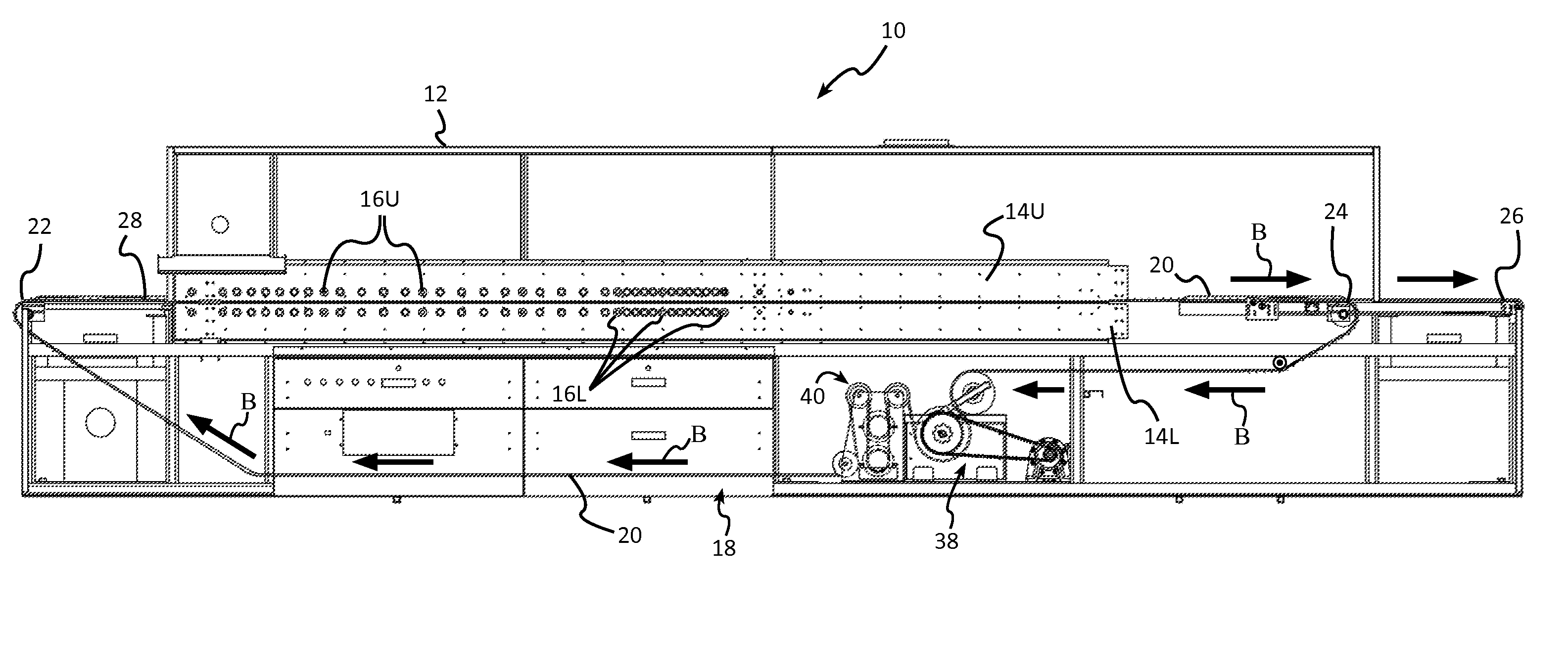
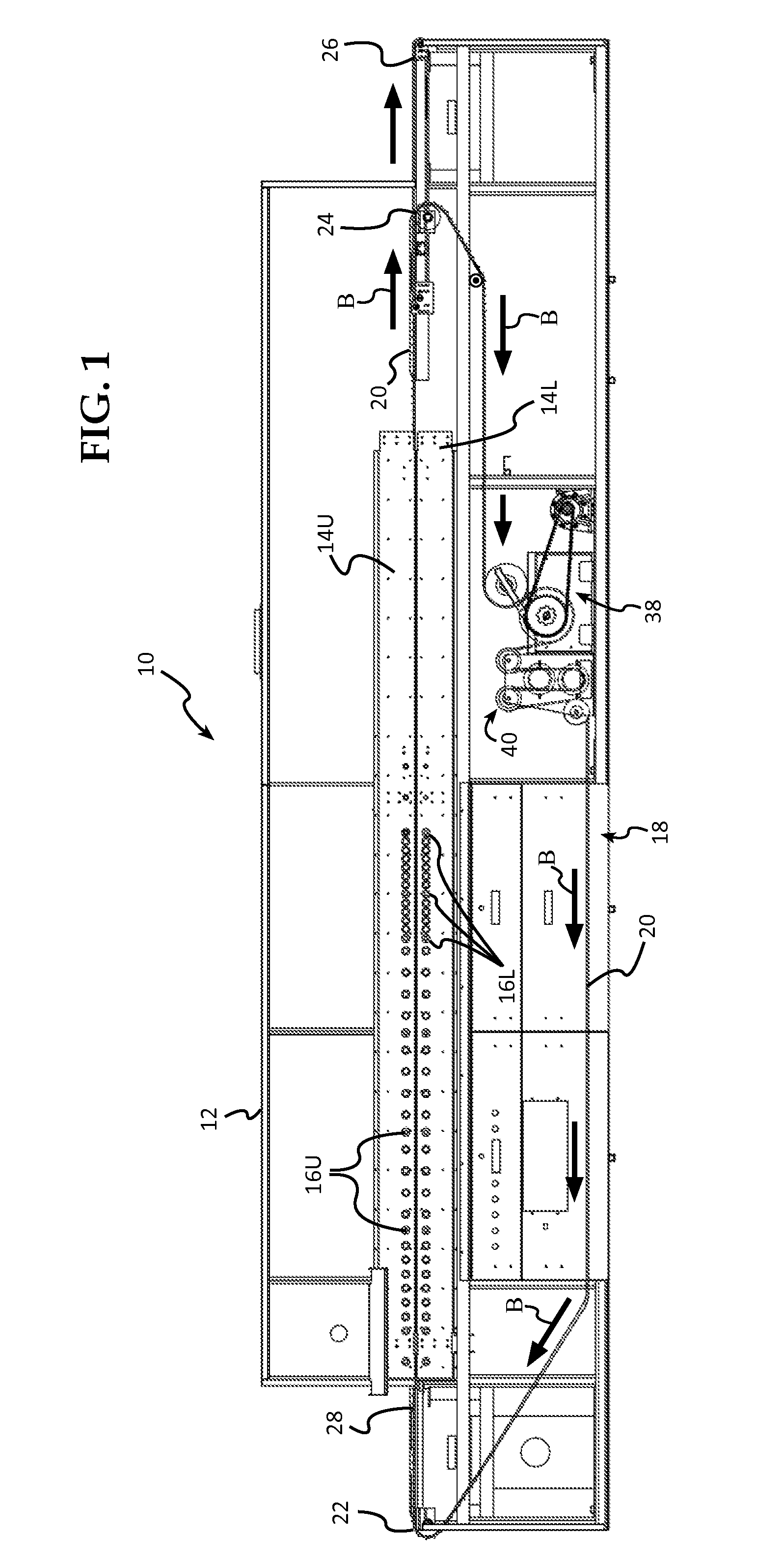
[0052]FIG. 1 shows a first embodiment of the inventive furnace 10 having a dual independent transport system 18, in this example shown as implemented in an IR lamp-heated conveyor furnace for treatment of thin Si wafers in at least one step of the process of converting them to solar cells. The work pieces, thin Si wafers 28, enter on the left and exit, after processing, on the right in FIG. 1, the heavy Arrows B showing the direction of travel during processing and return of the wafer transport belts.

[0053]The inventive transport system comprises a framewor...


PUM


Abstract

Multi-lane, side-by-side, independently driven transport systems particularly useful for transfer on conveyor belts or finger/chains of thin work pieces, such as silicon wafers, through processing equipment for converting the wafers into solar cells, including UV pre-treaters, dopers, dryers, diffusion furnaces and metallization furnaces. The inventive multi-lane transport systems may employ wire mesh belts having a flying bridge wafer support system comprising longitudinally spaced carrier wire elements that support the wafers at their side edges at only point contacts, by means of opposed, inwardly inclined, downwardly slanted segments or wings. Alternately, finger drives comprising spaced-apart chains having inwardly projecting fingers may be used for transport of the wafers by side edge contact. Friction or sprocket drives having tensioner assemblies associa-ted therewith are used to move the transport belts or finger chains through the furnace zones. Each lane may be independently controlled to provide unique thermal profiles along their processing paths.

Description

FIELD[0001]The invention is directed to furnace conveyor systems, and more importantly to dual, side by side, independently driven transport systems particularly useful for transfer on conveyor belts of thin work pieces, such as silicon wafers, through processing equipment for converting the wafers into solar cells, including UV pre-treaters, dopers, dryers, diffusion furnaces and metallization furnaces. The inventive transport system may use a wide range of conveyor belts, including a wire mesh belt having a flying bridge wafer support system comprising longitudinally spaced carrier wire “wing” elements that support the wafers at their side edges in only point contacts by means of opposed, inwardly inclined, downwardly slanted wafer support segments.BACKGROUND[0002]The fabrication of silicon-based photovoltaic solar cells from thin silicon wafers, typically 140-180 micrometers thick, requires multiple processing steps, including a 2-stage diffusion process to create a semi-conducti...

Claims


Application Information

Patent Timeline
Patent Type & Authority Applications(United States)
IPC IPC(8): F27D11/00B65G37/00
CPCF27B9/021F27B9/243F27B9/36H01L21/67115H01L21/67173H01L21/67736H01L21/6776
Inventor PARKS, RICHARD W.RAGAY, PETER G.REY GARCIA, LUIS ALEJANDRO
Owner TP SOLAR OF USA
Why Eureka
Try Eureka