[0011]The present disclosure achieves the above and other aspects by providing a flexible antenna for electronic devices, that can simplify the assembling process in the antenna integration, incorporating the surface
mount device technology in the antenna structure to a printed circuit board on the second substrate of the antenna onto the printed circuit board, having a plurality of first solder for physical attachment and a second solder pad electrically connected onto the printed circuit board for the
radio signal propagation. The flexible material is not deformed by the high temperatures in the surface mount process and / or not suffering any kind of shrinking effect in the substrate.
[0012]Suitable flexible material, such as material formed from polymerizing an aromatic dinahydride and an
aromatic diamine, commercially available as
Kapton®, can be used on antennas prepared according to this disclosure. The flexible material, such as
Kapton®, has a
dielectric constant of 3.8. The
total thickness of the flexible material ranges from 0.01 mm to 1.00 mm, and is approximately 0.085 mm in many configurations. The flexible material encloses the radiated elements. Using this flexible material for the
antenna design facilitates enclosing radiated elements with the flexible material, thus reducing the size of the antenna even with a thin form factor. Additionally, as the
electromagnetic field current travels on the surface of the radiated elements and interacts with the high
dielectric constant material, the thin material with high dielectric constant supports the radiated elements. Thus, it is almost imperceptible in compare with the air that surrounds the antenna which means the antenna is surrounded mainly by air, resulting in an effective dielectric constant (computation the two materials with different dielectric constant) very close to the free-space.
[0013]A stiffening component can be incorporated to assist a successful
surface mounting assembly procedure of the antenna to the device, it can be made by any
Flame Retardant 4 (FR-4) material or the UL-94-VO standard
polyimide attaching it to the antenna with a very fine glue or
adhesive material. This glue can afford the high temperature for the
surface mounting device (SMD) process. This stiffening component can be easily removed after the surface mount process when is concluded without leave any residue. Due the light in weight of the antenna could not be accurate to stay on its placed location on the device and / or too thin in thickness to maintain its proper structural shape during the entire procedure as consequence from violent pick-and-place movements for all components of the device-board. Usefulness of such as stiffening component is to provide overall
structural rigidity and add weight to the flexible antenna to maintain the placement in the SMD production, having an extra in weight pressing down the antenna and having a better contact, avoiding inaccurate
soldering.
[0014]A low profile flexible antenna in accordance with the present disclosure is based essentially on flexible circuit technology that is particularly useful when applied to mobile applications such as for
consumer electronic devices, having a unique characteristic where in one structure high performance, surface mountable and having different bending angles to conform different shapes are achieved, ending in easy, practical, cheap and time saving at the integration. Automated integration becomes possible avoiding labors such as
soldering and installation of
pogo pin and spring contacts, resulting in a reliable and consistence antenna performance and the present invention can be delivered on tapes and reels just like SMD diodes, resistors and others.
[0015]The complete
surface mount technology integration provided for enables an easy, cheap, time saving, and automated integration which eliminates the necessity of human interactions for
soldering purposes,
pogo pin and spring contacts. All of this assembling and integration qualities ends in delivering a reliable and consistence antenna performance, reflected on better
signal reception, making the antenna feasible for telematic, tracking, telemedicine, automotive,
fleet management, vehicle diagnostics, remote monitoring and also in the emerging telemedicine diagnostic market.
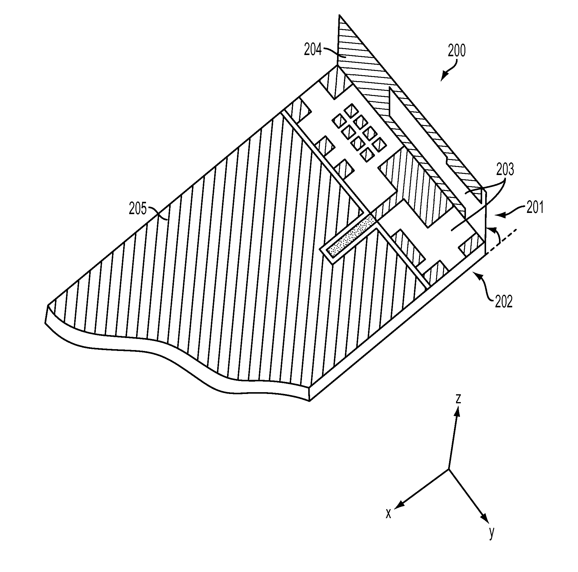
[0016]The antennas disclosed achieve a compact volume, with a minimum
footprint and can be placed into the housing of the
mobile device. Antennas can also be mounted directly on edge of device main-board. Transmission losses can be kept at a minimum resulting in much improved
over the air (OTA) device performance compared to similar efficiency cable and connector antenna solutions. Moreover, there is a reduction in backward
radiation toward the user's head compared to other antenna technologies, thus minimizing the electromagnetic
wave power absorption (SAR) which in turn enhances the antenna's performance. The antennas achieve a moderate to high
gain in both vertical and horizontal polarization planes. This feature is very useful in certain
wireless communications where the antenna orientation is not fixed and the reflections or multipath signals may be present from any plane. In those cases the important parameter to be considered is the
total field strength, which is the vector sum of the
signal from the
horizontal and vertical polarization planes at any instant in time. The antennas are configured to use labour saving SMT which facilitates a higher quality
yield rate and eliminates antenna tooling costs.INCORPORATION BY REFERENCE

