Electrochemical carbon nanotube filter and method

a carbon nanotube and filter technology, applied in the field of filtration apparatuses, can solve the problems of unsuitable drinking water, large specific surface area of porous elemental carbon anodes, and inability to efficiently perform electrochemical processes, and achieve the effect of reducing the resistance to flow

Active Publication Date: 2012-09-20
PRESIDENT & FELLOWS OF HARVARD COLLEGE
View PDF0 Cites 71 Cited by
  • Summary
  • Abstract
  • Description
  • Claims
  • Application Information

AI Technical Summary

Benefits of technology

[0021]In order to minimize the resistance to a flow through the laminated filter, in some embodiments, the porous polymer layer can exhibit a flux that is at least 70% of a flux through the

Problems solved by technology

Waterborne contaminants e.g., toxic chemical substances and pathogens, are a primary public health concern in developing countries and result in millions of deaths every year [1].
However, active chlorine-based pathogen inactivation can result in formation of harmful disinfection by-products [9], making the treated water unsuitable for drinking.
While the low driving potentials of these carbon-based anodes may reduce energy requirements and avoid disinfection by-product formation, these porous elemental carbon anodes do not have large specific surface area for efficient electrochemical processes.
However, the low mass transfer of contaminants from water to the electrode surface has limited the usefulness of electrochemical techniques in water treatment.
However, re-circulation of contaminated water through the system limits its usefulness in continuous free-flow processes.
Further, the Yang et al. reference does not disclose the ability of the system to remove biological microorganisms such as pathog

Method used


Image

  • Electrochemical carbon nanotube filter and method
  • Electrochemical carbon nanotube filter and method
  • Electrochemical carbon nanotube filter and method

Examples


example 1

Design and Operation of the Electrochemical Filter

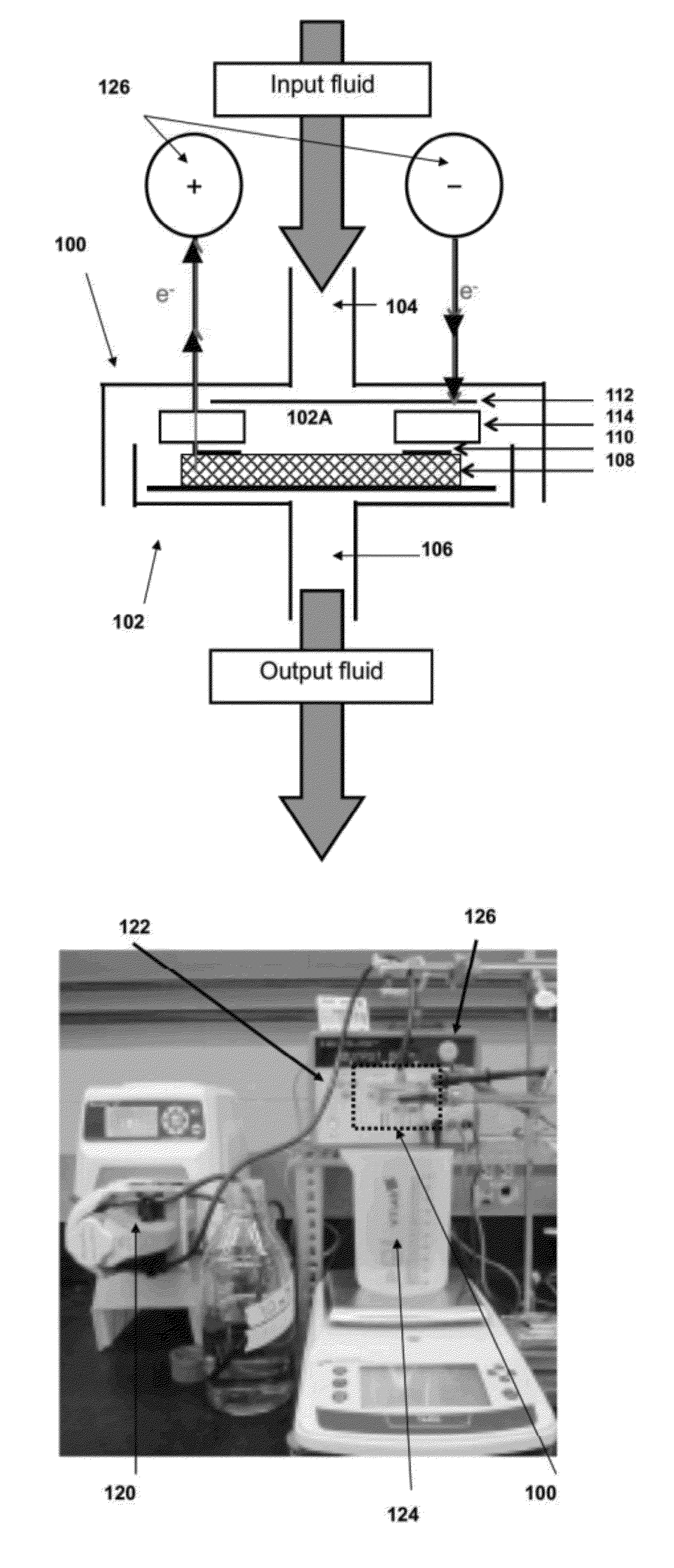
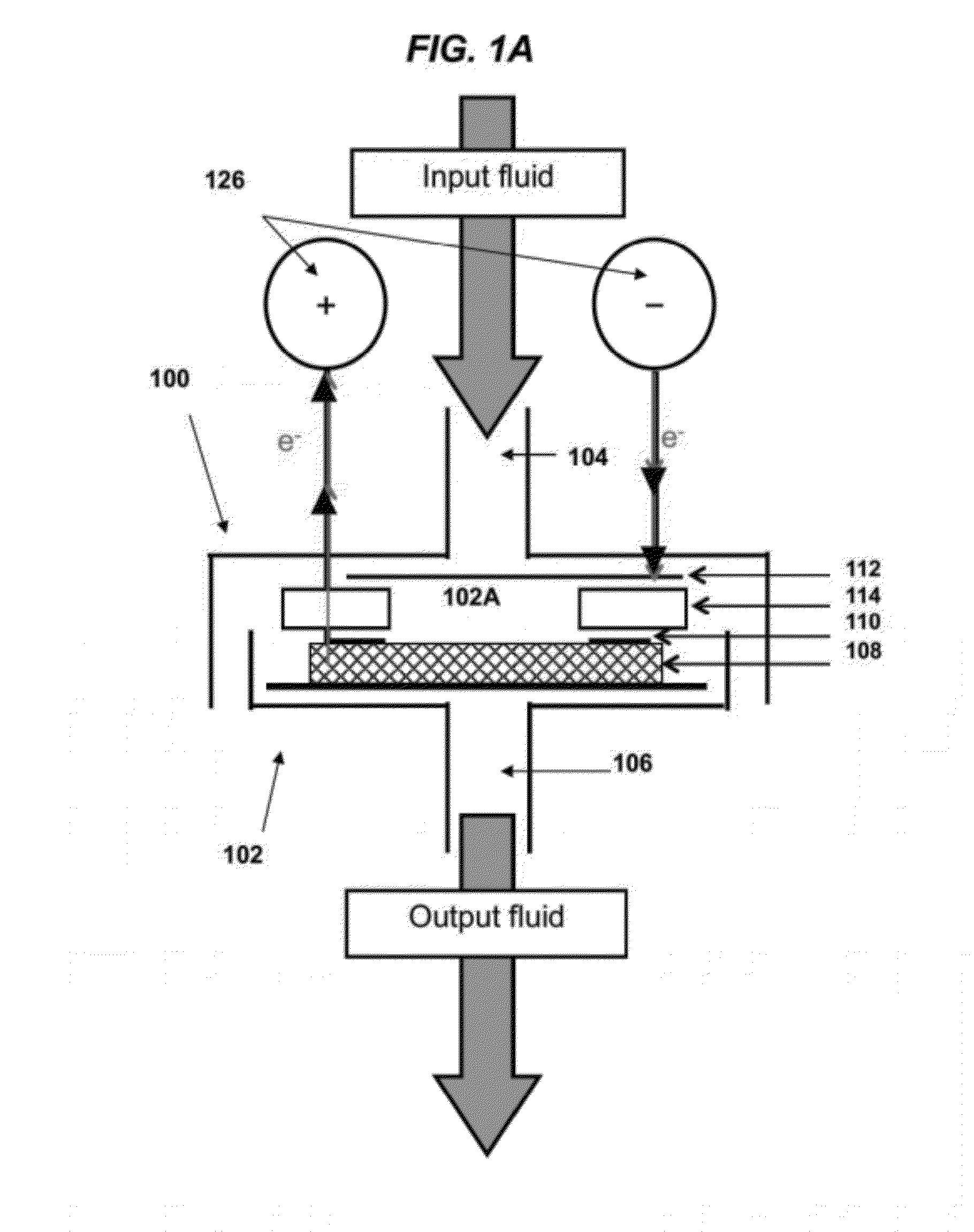
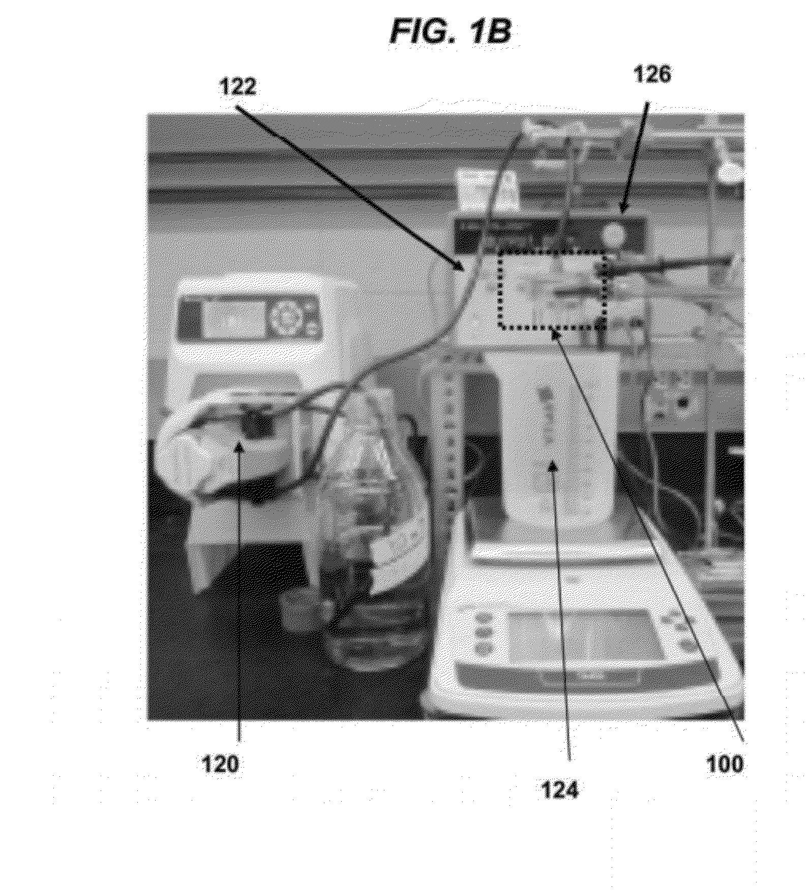
[0372]FIGS. 1A to 1G show images of one embodiment of the electrochemical filtration apparatus and set-up. A commercial 47 mm polycarbonate filtration casing (Whatman) as shown in FIG. 1C was modified to allow for simultaneous electrochemistry. Two holes were drilled in the upper piece of the filtration casing as openings for the cathodic and anodic leads. The main components of the electrochemical filter casing are the perforated stainless steel cathode (1) separated with an insulating silicone rubber seal (2) from the titanium (Ti) anodic ring-connector (3) (FIG. 1D). When the filtration casing is sealed, the anodic Ti ring (3) is pressed into the carbon nanotube filter (4) (FIG. 1E) for electrical connectivity. FIGS. 1F and 1G show images of the MWNT filters mats prior to and after electrochemical filtration, respectively.

[0373]FIG. 2A to 2F show both aerial and cross-section SEM images of the MWNT filter. The MWNT mat is composed...

example 2

Dye Adsorption to the MWNT Filter in the Absence of an Applied Voltage

[0375]FIG. 4A shows a schematic diagram of dye adsorption to the MWNT filter and FIG. 4B shows the methylene blue (MB) adsorption breakthrough curve, [MB]eff / [MB]in vs. t, in the absence of electrochemistry for three MWNT filters of varying physical dimensions ([MB]in=7.0±1.0 μM, [NaCl]in=10 mM, J=1.5±0.1 mL min−1). The squares, circles, and triangles represent filters having average height (h) and diameter (d) of h=41 μm and d=30 mm, h=68 μm and d=30 mm, and h=41 μm and d=40 mm, respectively. In all cases, the methylene blue concentration of the output fluid was below the limit of detection prior to breakthrough, indicating that all MB molecules had at least one collision that could result in sorption with the MWNT surface during a single pass through the filter of ≦1.2 s. Images of the filtration set-up during the MB adsorption process are shown in FIG. 5. The MB sorption capacities of the three filters were 28....

example 3

Electrochemical Desorption and / or Oxidation of Adsorbed Dye

[0378]Due to the thin film nature of the filter, the total adsorptive capacity of the MWNT filter is relatively low, i.e., dye breakthrough occurs in eff / [MB]in>1, suggesting that the adsorbed MB is electrostatically desorbed. Without wishing to be bound by theory, anodic operation of the MWNT filter can result in accumulation of positively charged holes at the anode surface and / or generation of protons near the MWNT interface. Accordingly, positively-charged methylene blue at the unbuffered pH 6.3 used for the experiments described herein can be electrostatically desorbed. The increase in MB concentration of the output fluid was correlated with the applied potential, i.e., [MB]eff / [MB]in at about 3 volts=˜20)>[MB]eff / [MB]in at about 2 volts=˜6)>[MB]eff / [MB]in at about 1 volt=˜2), which is consistent with an electrostatic desorption mechanism. In all cases, upon continued electrolysis, the [MB]eff / [MB]in quickly decreased un...


PUM

PropertyMeasurementUnit
Fractionaaaaaaaaaa
Pore sizeaaaaaaaaaa
Pore sizeaaaaaaaaaa

Abstract

A filtration apparatus and filtration method can be used to reduce at least one contaminant (e.g., organic molecules, ions and/or biological microorganisms) in an aqueous fluid. The filtration apparatuses and methods of the invention can separate at least one contaminant from an aqueous fluid and/or oxidize at least one contaminant. In operation, an aqueous fluid is flowed through a filtration apparatus comprising a porous carbon nanotube filter material at an applied voltage. In some embodiments, the filtration apparatus described herein can be used for dead-end filtration. In some embodiments, the filtration apparatus described herein can be used for cross-over filtration.

Description

CROSS-REFERENCE TO RELATED APPLICATIONS[0001]This application claims benefit under 35 U.S.C. §120 and is a Continuation-in-Part of U.S. application Ser. No. 13 / 358,248, filed Jan. 25, 2012, which claims benefit under 35 U.S.C. §119(e) of provisional application No. 61 / 436,031, filed on Jan. 25, 2011. The contents of both applications are incorporated herein by reference in their entirety.FIELD OF THE INVENTION[0002]The invention relates generally to filtration apparatuses and methods for reducing one or more contaminants from a fluid, e.g., an aqueous fluid. In particular, the invention is directed to filtration apparatuses and methods using an applied voltage for reducing aqueous contaminants.BACKGROUND OF THE INVENTION[0003]Waterborne contaminants e.g., toxic chemical substances and pathogens, are a primary public health concern in developing countries and result in millions of deaths every year [1]. Minimal drinking water treatment is beneficial and should include removal of harm...

Claims


Application Information

Patent Timeline
IPC IPC(8): B01D35/06B01J19/08B01D29/56B82Y30/00
CPCB01D39/2055B01D2239/065B82Y30/00B01D35/06
Inventor VECITIS, CHAD D.VAN FOSSEN, KIRSTEN
Owner PRESIDENT & FELLOWS OF HARVARD COLLEGE
Why Eureka
Try Eureka