Adhesive film and flat cable using same
a technology of adhesive film and flat cable, applied in the direction of film/foil adhesive primer layer, cables, insulated conductors, etc., can solve the problems of difficult extrusion thin and uniformly, high production cost in comparison with wet coating, and high melt viscosity of base resin, etc., to enhance adhesion and excellent heat resistance
- Summary
- Abstract
- Description
- Claims
- Application Information
AI Technical Summary
Benefits of technology
Problems solved by technology
Method used
Image

Examples
first embodiment
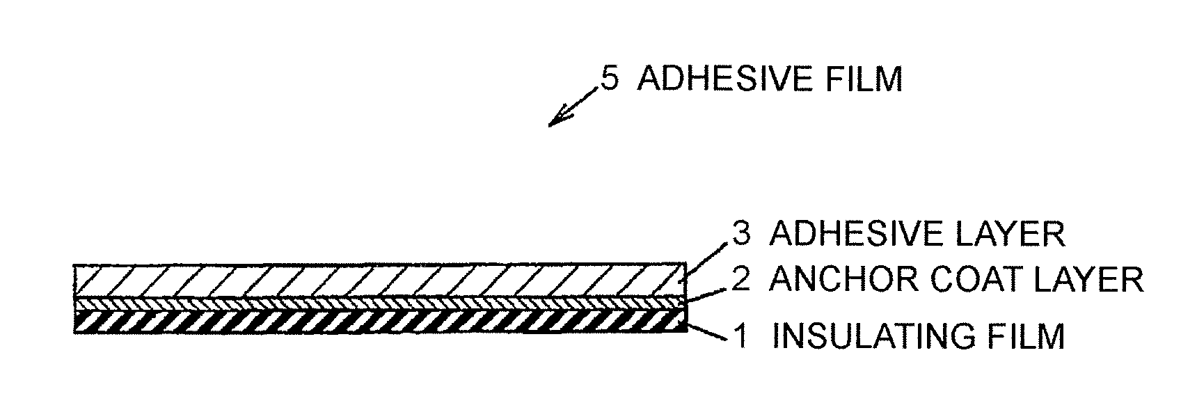
Adhesive Film 5 Structure
[0054]Referring to FIG. 1, there is shown a cross sectional view showing one example of a structure of an adhesive film 5 in a first embodiment according to the invention. As shown in FIG. 1, this adhesive film 5 includes an insulating film 1, an anchor coat layer 2 formed over one side of the insulating film 1, and an adhesive layer 3 formed over the anchor coat layer 2.
Insulating Film 1
[0055]As the suitable insulating film 1, an engineering plastic is used. For example, there can be used a polyester resin, aromatic polycarbonate resin, polyphenylene sulfide resin, polyimide resin, polyetherimide resin, or the like. As examples of the polyester resin, there are listed the following: polyethylene terephthalate resin, polybutylene terephthalate resin, polyethylene naphthalate resin, polybutylene naphthalate resin, polytrimethylene terephthalate resin, polytrimethylene naphthalate resin, polycyclohexane dimethyl terephthalate resin, polycyclohexane dimethyl na...
second embodiment
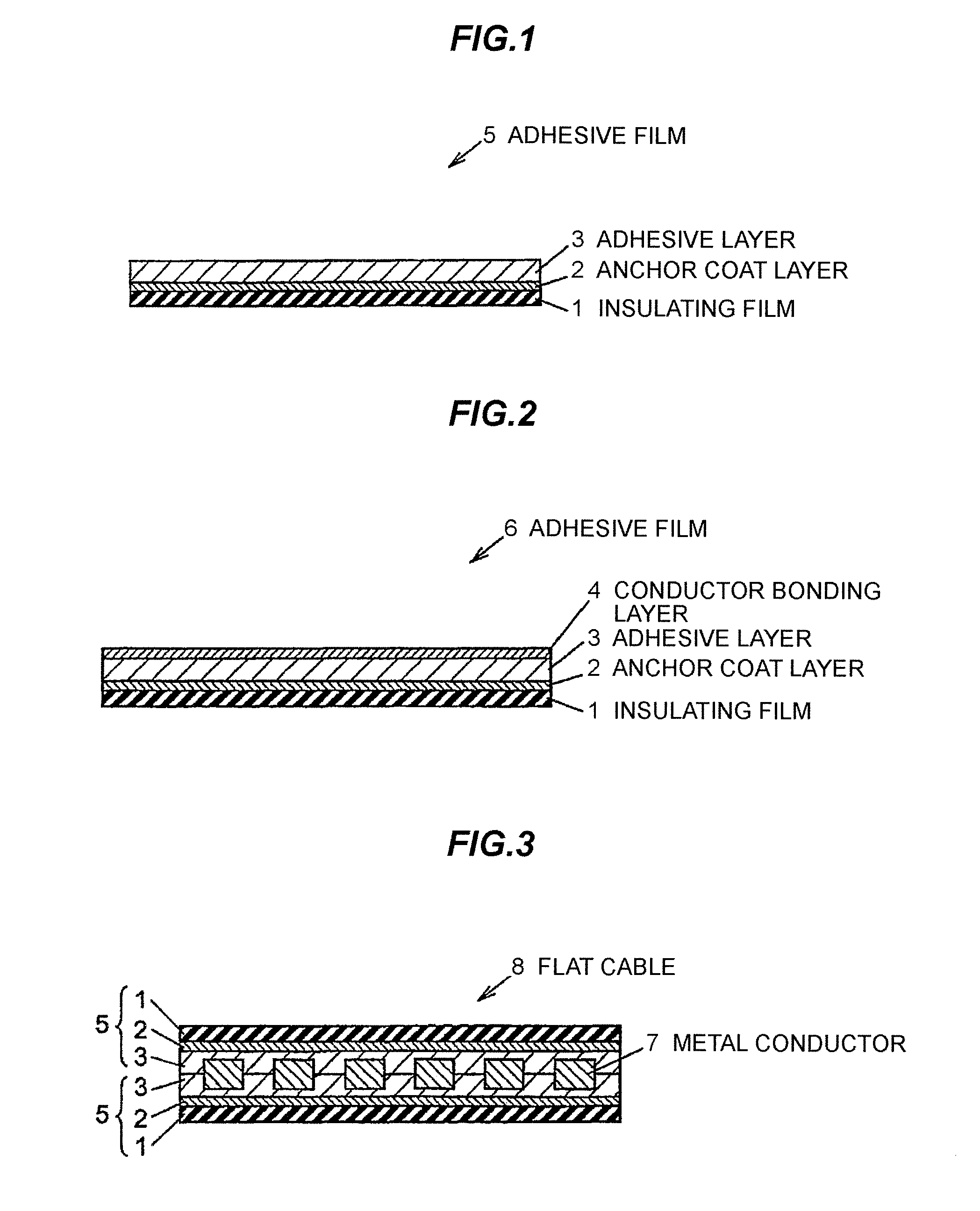
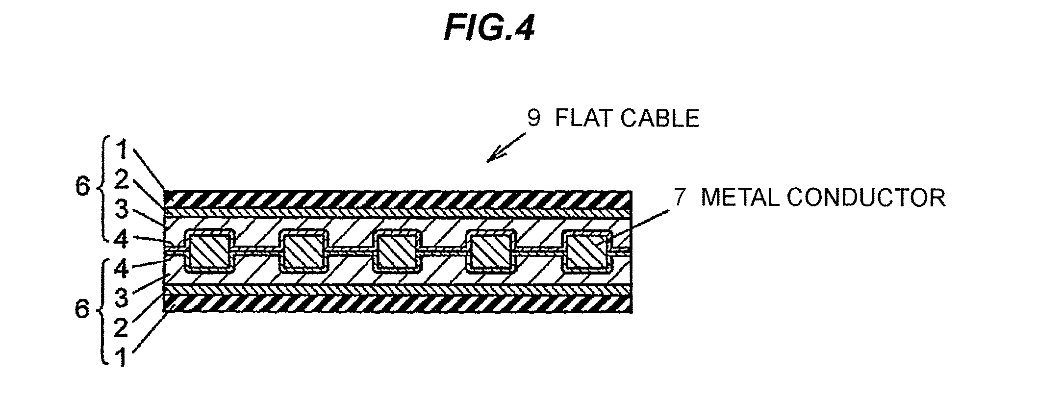
Structure of Adhesive Film 6
[0069]Referring to FIG. 2, there is shown a cross sectional view showing one example of an adhesive film 6 in a second embodiment according to the invention. This adhesive film 6 includes the insulating film 1, the anchor coat layer 2 and the adhesive layer 3 which constitute the adhesive film 5 as shown in FIG. 1, and a further conductor bonding layer 4 formed over the adhesive layer 3 of the adhesive film 5, and the conductor bonding layer 4 is bondable with a metal conductor.
[0070]Although the adhesive layer 3 is constructed in the same manner as in the first embodiment, the additive amount of the flame retardant added to the adhesive layer 3, when provided with the conductor bonding layer 4 thereover, is not less than 120 parts by weight and not more than 200 parts by weight, relative to 100 parts by weight of the resin.
Conductor Bonding Layer 4
[0071]A base resin for constituting the conductor bonding layer 4 can use a resin which is soluble in a halo...
third embodiment
Structure of Flat Cable 8
[0075]Referring to FIG. 3, there is shown a cross sectional view showing one example of a structure of a flat cable 8 in a third embodiment according to the invention. This flat cable 8 is formed by use of the adhesive film 5 as shown in FIG. 1. That is, the flat cable 8 is formed by arranging the two adhesive films 5 so that their respective adhesive layers 3 face each other, arranging a plurality of metal conductors 7 parallel to each other between the adhesive layers 3, and thereafter bonding the adhesive layers 3 together with a laminator.
[0076]The metal conductors 7 can use an electrically conductive material, such as a copper based material made of a copper or a copper alloy, an iron based material made of an iron or an iron alloy, an aluminum based material made of aluminum or an aluminum alloy, or the like. As examples of the copper based material, there are listed the following: oxygen free copper, tough pitch copper, phosphor bronze and the like. A...
PUM
| Property | Measurement | Unit |
|---|---|---|
| Percent by mass | aaaaa | aaaaa |
| Percent by mass | aaaaa | aaaaa |
| Percent by mass | aaaaa | aaaaa |
Abstract
Description
Claims
Application Information