Lithium-ion rechargeable battery module, vehicle with the battery module and generating system with the battery module

a rechargeable battery and battery module technology, applied in secondary cell details, sustainable manufacturing/processing, batteries, etc., can solve the problems of insufficient improvement of high-temperature storage characteristics of battery cells, insufficient high-temperature storage characteristics, and inability to prevent temperature rise at high temperature portions, etc., to achieve good high-temperature storage characteristics, reduce capacity, and resist the effect of increasing

Inactive Publication Date: 2012-10-18
HITACHI LTD
View PDF5 Cites 6 Cited by
  • Summary
  • Abstract
  • Description
  • Claims
  • Application Information

AI Technical Summary

Benefits of technology

[0040]Methods for obtaining a battery cell with a high resistance and a good high-temperature storage characteristic for use on an high temperature portion will be explained as follows. The cause of deterioration at high temperatures, such as diminished capacity and resistance increase, is mainly the reaction between the electrolyte and the negative electrode. In preventing such degradations at high temperatures, it is therefore effective to form a firm protective film over the negative electrode and enhance the stability of the electrolyte.
[0041]To form a strong protective film, one method puts additives, such as vinylene carbonate (VC), in the electrolyte. It is noted that the amount of these additives has been limited to 5 wt % because they increase the battery cell resistance. However, since some resistance is required for those cells used on a high temperature portion in this invention, the use of additives at more than 5 wt %, or even 10 wt % or more, is allowed.
[0042]In one method of enhancing the stability of the elec

Problems solved by technology

While JP-A-2005-32701 describes additives for improving the storage characteristics at high temperatures, since the additives also increase a resistance, their amounts are necessarily limited.
So, the improvement of the high-temperature storage characteristics of the battery cells is not enough.
Although the battery module descr

Method used


Image

  • Lithium-ion rechargeable battery module, vehicle with the battery module and generating system with the battery module
  • Lithium-ion rechargeable battery module, vehicle with the battery module and generating system with the battery module
  • Lithium-ion rechargeable battery module, vehicle with the battery module and generating system with the battery module

Examples


embodiment 1

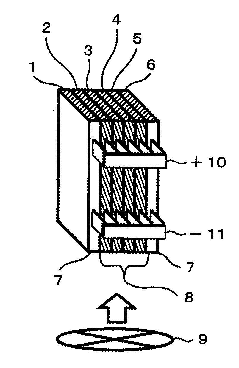
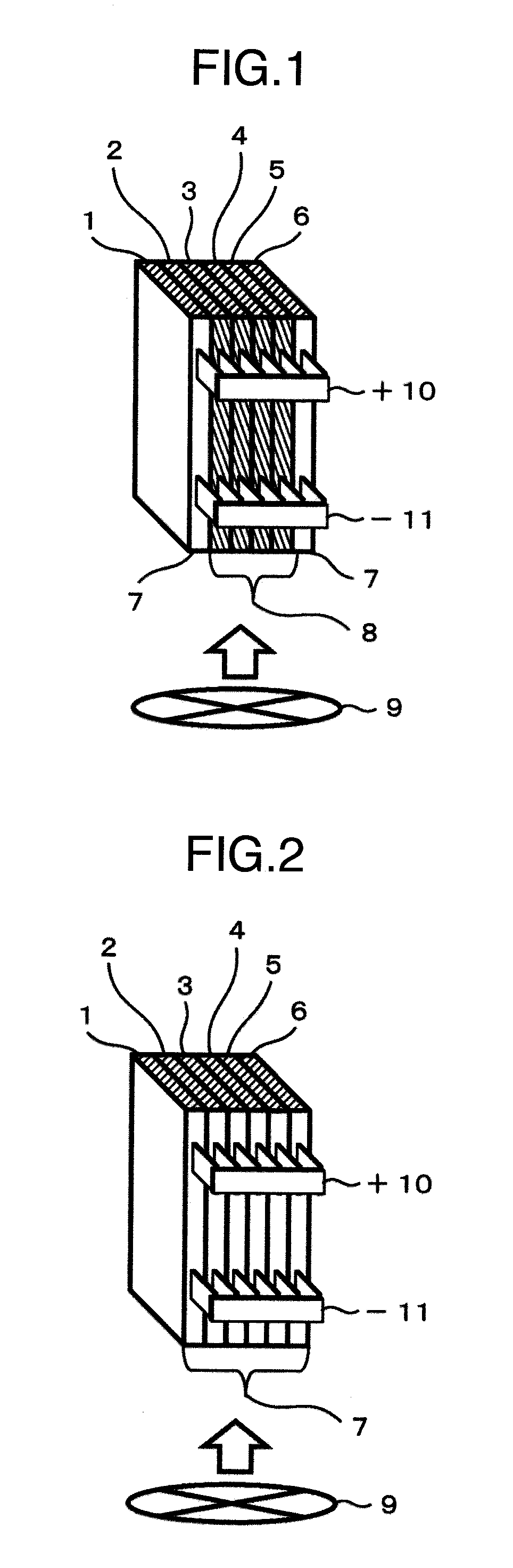
[0045](Battery Module Construction of Embodiment 1)

[0046]The construction of an embodiment 1 is shown in FIG. 1. Lithium-ion battery cells 1-6 were laminate sheet type cells each 6.5 mm thick. Six of these lithium-ion cells were stacked together and electrically connected in parallel to form a battery module. Of the six stacked cells, four at the center exposed to high temperatures (cells 2-5 in FIG. 1) were high resistance heat-tolerant battery cells 8 with higher VC and EC concentrations in the electrolyte than the two normal battery cells 7 installed at the ends of the module (cells 1, 6 in FIG. 1). The high resistance heat-tolerant battery cells 8 were found to be about 1.2 times higher in resistance at 20° C. and have a higher capacity retention rate when stored at 50° C. than the normal cells 7. The maximum allowable temperatures, with the battery cell longevity taken into account, were set at 50° C. for the high resistance heat-tolerant cells 8 and 45° C. for the normal cells...

embodiment 2

[0059](Battery Module Construction of Embodiment 2)

[0060]The construction of a second embodiment is shown in FIG. 7. A cylindrical cell 67 mm in diameter was used for the lithium-ion cell. The cylindrical cells were arrayed in five layers stacked one upon the other vertically, with the vertically arranged cells electrically connected in parallel and the horizontally arranged cells connected in series. These cells were spaced 10 mm from one another vertically and horizontally. They were cooled by the cooling fan 9 blowing air against them at 1.5 m / s.

[0061]Of the vertically arranged cells, those in upper two tiers (fourth and fifth tier in FIG. 7) that are heated to high temperatures employed high resistance heat-tolerant cells 8 having higher VC and EC concentrations in the electrolyte than those of normal cells 7 located at a central portion (second and third tier in FIG. 7). The high resistance heat-tolerant cells 8 was found to be about 1.5 times higher in resistance at 20° C. and...

embodiment 3

[0068]The lithium-ion rechargeable battery module shown in the embodiment 1 and the embodiment 2 can be used as a power supply for a variety of vehicles, such as hybrid trains that travel on both engine and motor, electric cars using batteries as an energy source for motor; hybrid cars, plug-in hybrid cars whose batteries can be charged by external sources, and fuel cell cars that derive electric energy from the chemical reaction between hydrogen and oxygen.

[0069]A schematic plan view of a typical drive system for an electric car (vehicle) 30 is shown in FIG. 13.

[0070]An electric energy is supplied from a battery module 16 through a battery controller and a motor controller, both not shown, to a motor 17 to drive the electric car 30. During deceleration, an electric energy regenerated by the motor 17 is stored in the battery module 16 through the battery controller.

[0071]The application of the battery module 16 of this invention to an electric car (vehicle) 30 as in the embodiment 3...


PUM


Abstract

A lithium-ion rechargeable battery module having a plurality of lithium-ion battery cells, arranged that battery cells located at an high temperature portion of the module are electrically connected in parallel with battery cells located at a low temperature portion of the module. The battery cells at the high temperature portion have a higher electric resistance at 20° C. and a better high-temperature storage characteristic at 50° C. than those of the battery cells located at the low temperature portion.

Description

BACKGROUND OF THE INVENTION[0001]The present invention relates to a lithium-ion battery module composed of a plurality of lithium-ion rechargeable battery cells, and to a vehicle and a generating system using such battery modules.[0002]For the prevention of global warming and from concerns that fossil fuels may be exhausted in the near future, expectations have been growing in recent years for large-scale rechargeable battery modules, such as car-mounted rechargeable battery modules used on hybrid cars and electric cars running on a relatively small amount of energy and stationary rechargeable battery modules for smoothing the output of generating systems operating on renewable energies such as solar and wind power. These rechargeable battery modules are required to have both a high output density and a high energy density.[0003]Because of its excellent properties in both the output density and energy density when compared with other battery modules using nickel-metal hydride rechar...

Claims


Application Information

Patent Timeline
IPC IPC(8): H01M10/02H01M10/04H01M2/20
CPCH01M10/0525H01M10/0569H01M10/058Y02T10/7011H01M2220/20Y02E60/122H01M2220/10Y02E60/10Y02P70/50Y02T10/70
Inventor GUNJI, AKIRATAKAHASHI, SHINIWASAWA, HIROSHIYAMAUCHI, SHINOKUMURA, TAKEFUMI
Owner HITACHI LTD
Why Eureka
Try Eureka