Stress Regulated Semiconductor Devices and Associated Methods

a technology of stress regulation and semiconductor devices, applied in semiconductor devices, semiconductor/solid-state device details, electrical apparatus, etc., can solve problems such as various thermal problems, increase in speed and decrease in size of electronic circuitry, and difficulty in cooling such devices

Inactive Publication Date: 2012-11-08
RITEDIA CORPORATION
View PDF6 Cites 14 Cited by
  • Summary
  • Abstract
  • Description
  • Claims
  • Application Information

AI Technical Summary

Benefits of technology

[0006]Accordingly, the present invention provides stress regulated semiconductor devices and associated methods thereof. In one aspect, for example, a stress regulated semiconductor device can include a semiconductor layer, a stress regulating interface layer including a carbon layer bonded to the semiconductor layer by a carbide former, and a heat spreader coupled to the stress regulating interface layer opposite the semiconductor layer. The stress regulating interface layer is operable to reduce the coefficient of thermal expansion difference between the semiconductor layer and the heat spreader to less than or equal to about 10 ppm / ° C. In another aspect, the stress regulating interface layer is operable to reduce the coefficient of thermal expansion difference between the semiconductor layer and the heat spreader to less than or equal to about 5 ppm / ° C.
[0011]In another aspect of the present invention, a stress regulated semiconductor device is provided. Such a device can include a semiconductor layer and a heat spreader formed on the semiconductor layer, where the heat spreader includes diamond particles uniformly disposed within a metal matrix. The diamond particles are operable to reduce the coefficient of thermal expansion difference between the semiconductor layer and the metal matrix to less than or equal to about 10 ppm / ° C. In another aspect, the diamond particles are operable to reduce the coefficient of thermal expansion difference between the semiconductor layer and the metal matrix to less than or equal to about 5 ppm / ° C. In yet another aspect of the present invention, a stress regulated semiconductor device is provided. Such a device can include a semiconductor layer, an electrically conductive boron nitride layer formed on the semiconductor layer, and a heat spreader coupled to the boron nitride layer opposite the semiconductor layer. The boron nitride layer is operable to reduce the coefficient of thermal expansion difference between the semiconductor layer and the heat spreader to less than or equal to about 10 ppm / ° C.
[0012]In a further aspect of the present invention, a method for reducing stress induced defects in a semiconductor device is provided. Such a method can include forming a stress regulating interface layer including a carbon layer on a semiconductor layer, and coupling a heat spreader layer to the stress regulating interface layer opposite the semiconductor layer. In some aspects, coupling the heat spreader to the stress regulating interface layer includes forming the heat spreader on the stress regulating interface layer. The stress regulating interface layer reduces the coefficient of thermal expansion difference between the semiconductor layer and the heat spreader to less than or equal to about 10 ppm / ° C. In another aspect, the method can further include forming a reflective layer between the stress regulating interface layer and the semiconductor layer. In a more specific aspect, the method can further include forming a carbide former layer between the carbon layer and the reflective layer. In yet another aspect, the method can include forming a carbide former layer between the carbon layer and the metal heat spreader layer.

Problems solved by technology

As electronic circuitry increases in speed and decreases in size, cooling of such devices becomes problematic.
As it builds, heat can cause various thermal problems associated with such electronic components.
Significant amounts of heat can affect the reliability of an electronic device, or even cause it to fail by, for example, causing burn out or shorting both within the electronic components themselves and across the surface of the printed circuit board.
Thus, the buildup of heat can ultimately affect the functional life of the electronic device.
This is particularly problematic for electronic components with high power and high current demands, as well as for the printed circuit boards that support them.
As increased speed and power consumption cause increasing heat buildup, such cooling devices generally must increase in size to be effective and may also require power to operate.
The demand for smaller electronic devices, however, not only precludes increasing the size of such cooling devices, but may also require a significant size decrease.

Method used


Image

  • Stress Regulated Semiconductor Devices and Associated Methods
  • Stress Regulated Semiconductor Devices and Associated Methods
  • Stress Regulated Semiconductor Devices and Associated Methods

Examples


example 1

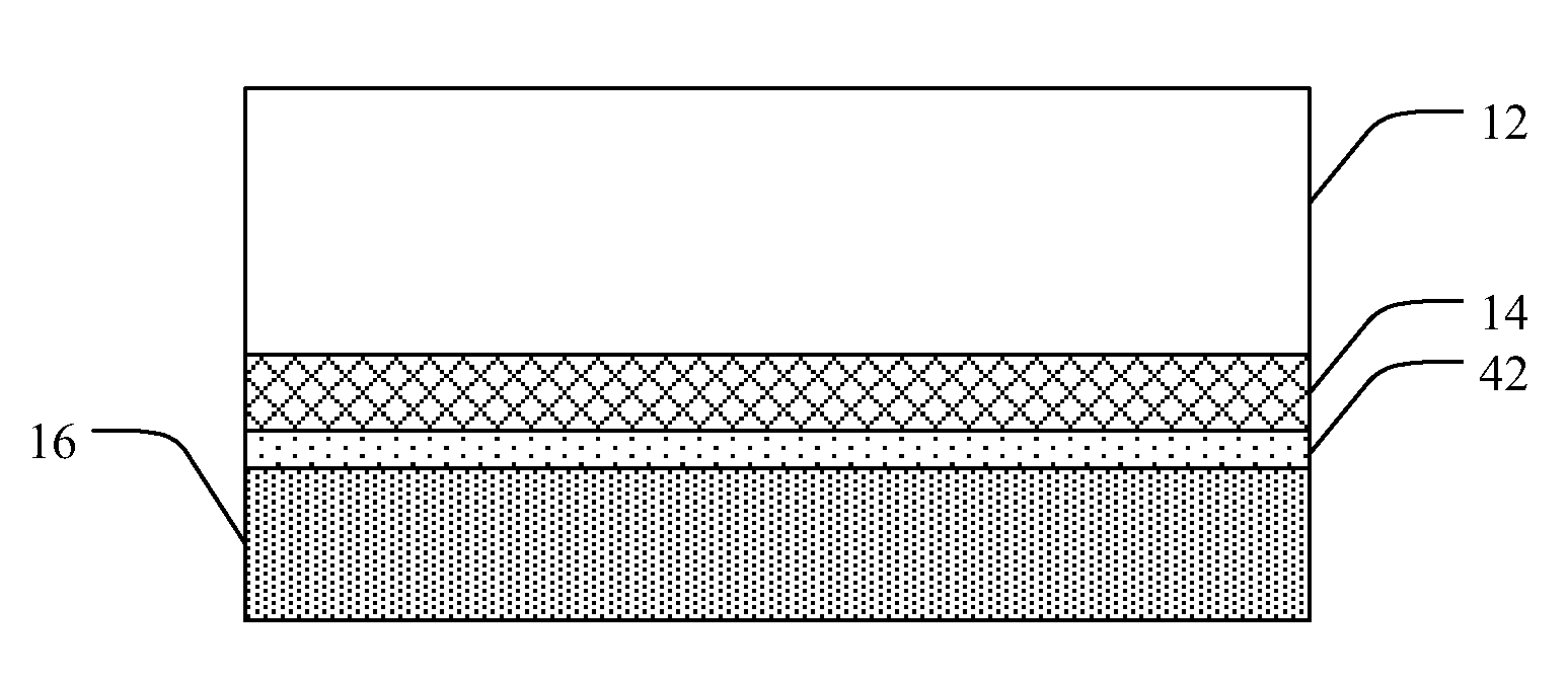
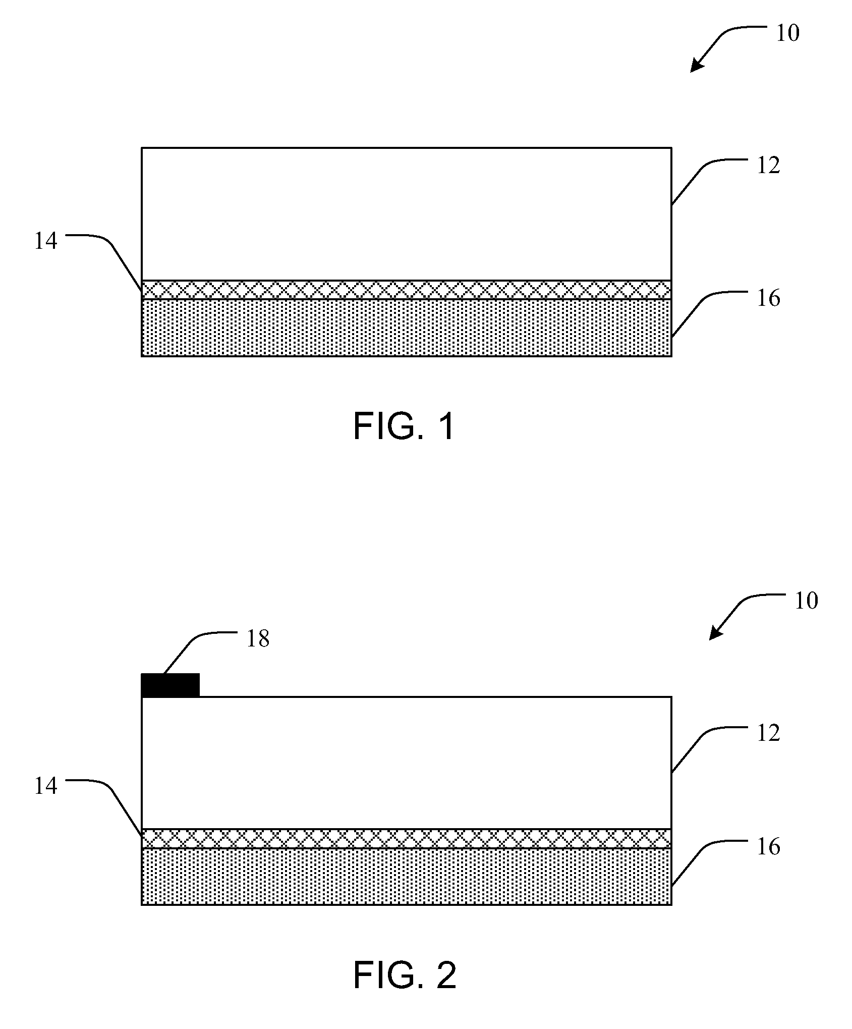
[0076]A 2 inch sapphire wafer is deposited with epitaxial GaN by MOCVD (metal organic chemical vapor deposition). Trimethylgallium is used as the Ga source gas and ammonia is added to supply nitrogen atoms. Hydrogen is also added in order to dilute the gas and to gasify Ga or N atoms if they are located in unstable sites on the lattice. A multiple layered semiconductor structure is made by n-doping with Si on the sapphire followed by p-doping with Mg to form a junction. Quantum wells and intrinsic layers can be introduced between the p-doped layer and the n-doped layer. The top surface of the p-doped layer is sputtered with a reflective layer of Ag to a thickness of about 200 nm. The reflective layer is then sputtered with a nucleation enhancing layer of Ti to about 50 nm thick.

[0077]Subsequently, amorphous diamond is deposited on the nucleation enhancing layer to a thickness of about 1 μm by cathodic arc deposition. An additional nucleation enhancing layer of Ti is sputtered on the...

example 2

[0078]A 2 inch sapphire wafer is deposited with epitaxial GaN by MOCVD (metal organic chemical vapor deposition). Trimethylgallium is used as the Ga source gas and ammonia is added to supply nitrogen atoms. Hydrogen is also added in order to dilute the gas and to gasify Ga or N atoms if they are located in unstable sites on the lattice. A multiple layered semiconductor structure is made by n-doping with Si on the sapphire followed by p-doping with Mg to form a junction. Quantum wells and intrinsic layers can be introduced between the p-doped layer and the n-doped layer.

[0079]The top surface of the p-doped layer is cosputtered with graphite and Ag to form a reflective layer. The graphite acts to reduce the CTE of the reflective layer. In this case, the CTE can be graded by controlling Ag / C ratio. Ag coating is then resumed without graphite. The Ag layer is then thickened by electroplating with Cu or Ag.

example 3

[0080]A 2 inch sapphire wafer is deposited with epitaxial GaN by MOCVD (metal organic chemical vapor deposition). Trimethylgallium is used as the Ga source gas and ammonia is added to supply nitrogen atoms. Hydrogen is also added in order to dilute the gas and to gasify Ga or N atoms if they are located in unstable sites on the lattice. A multiple layered semiconductor structure is made by n-doping with Si on the sapphire followed by p-doping with Mg to form a junction. Quantum wells and intrinsic layers can be introduced between the p-doped layer and the n-doped layer.

[0081]The top surface of the p-doped layer is cosputtered with graphite and Ag to form a reflective layer. The graphite acts to reduce the CTE of the reflective layer. In this case, the CTE can be graded by controlling Ag / C ratio. Ag coating is then resumed without graphite. A monolayer of micron diamond particles is spread across the Ag layer, and a Cu layer is electroplated there upon to incorporate the diamond part...


PUM

PropertyMeasurementUnit
bond lengthaaaaaaaaaa
thickaaaaaaaaaa
thickaaaaaaaaaa

Abstract

Stress regulated semiconductor devices and associated methods are provided. In one aspect, for example, a stress regulated semiconductor device can include a semiconductor layer, a stress regulating interface layer including a carbon layer formed on the semiconductor layer, and a heat spreader coupled to the carbon layer opposite the semiconductor layer. The stress regulating interface layer is operable to reduce the coefficient of thermal expansion difference between the semiconductor layer and the heat spreader to less than or equal to about 10 ppm / ° C.

Description

PRIORITY DATA[0001]This application claims the benefit of U.S. Provisional Patent Application Ser. No. 61 / 408,447, filed on Oct. 29, 2010, which is incorporated herein by reference in its entirety. This application also is also a continuation-in-part of U.S. patent application Ser. No. 13 / 239,189, filed on Sep. 21, 2011, which claims the benefit of U.S. Provisional Patent Application Ser. Nos. 61 / 384,976 and 61 / 468,917, filed on Sep. 21, 2010 and Mar. 29, 2011 respectively, all of which are incorporated herein by reference.FIELD OF THE INVENTION[0002]The present invention relates generally to semiconductor devices and associated methods. Accordingly, the present invention involves the electrical and material science fields.BACKGROUND OF THE INVENTION[0003]In many developed countries, major portions of the populations consider electronic devices to be integral to their lives. Such increasing use and dependence has generated a demand for electronics devices that are smaller and faster...

Claims


Application Information

Patent Timeline
Patent Type & Authority Applications(United States)
IPC IPC(8): H01L23/34H01L29/24H01L29/20H01L33/64
CPCH01L23/3732H01L23/3733H01L33/641H01L2933/0075H01L2924/0002H01L2924/00
Inventor SUNG, CHIEN-MINKAN, MING CHIKU, SHAO CHUNG
Owner RITEDIA CORPORATION
Why Eureka
Try Eureka