Solar cogeneration vessel

a cogeneration vessel and solar energy technology, applied in the direction of machines/engines, electric devices, process and machine control, etc., can solve the problems of reducing the power efficiency of photovoltaic cells, increasing substrate temperature may exponentially shorten the durability of photovoltaic cells for a given set of environmental conditions, and reducing the levelized cost of energy (lcoe). , the effect of eliminating the cost of land us

Inactive Publication Date: 2012-12-27
INTEGRATED POWER TECH CORP
View PDF14 Cites 42 Cited by
  • Summary
  • Abstract
  • Description
  • Claims
  • Application Information

AI Technical Summary

Benefits of technology

[0015]The present invention reduces the Levelized Cost Of Energy (LCOE) typically associated with solar power systems by primarily eliminating cost of land use in the form of both land lease agreements, and unpredictable up-front regulatory compliance costs such as environmental impact studies. Similarly, the present invention minimizes another factor in the Levelized Cost of Energy (LCOE) calculation that arises from maintenance and operations cost. Because under all cases less severe than catastrophic failure, a mobile structure can always return to a central service facility co-located with distribution where a small crew performs maintenance procedures in an assembly line manner as opposed to a more costly field crew working in potentially harsh environments. Also during the process of energy delivery itself, the mobile structure can continue to extract and store energy from the environment, substantially enhancing overall system energy production.
[0016]As an extension of the U.S. Pat. No. 7,698,024 and its continuation patent application Ser. No. 13/073,891 herein incorporated by reference, an addition to the SCADA server side applications which access a Geographic Information ...

Problems solved by technology

Concentrating Photovoltaic (CPV) systems suffer deleterious effects from heat generation.
Because photovoltaic cells operate under the principle of photons bombarding a semiconductor therein liberating electrons, and electron mobility diminishes inversely proportio...

Method used


Image

  • Solar cogeneration vessel
  • Solar cogeneration vessel
  • Solar cogeneration vessel

Examples


Embodiment Construction

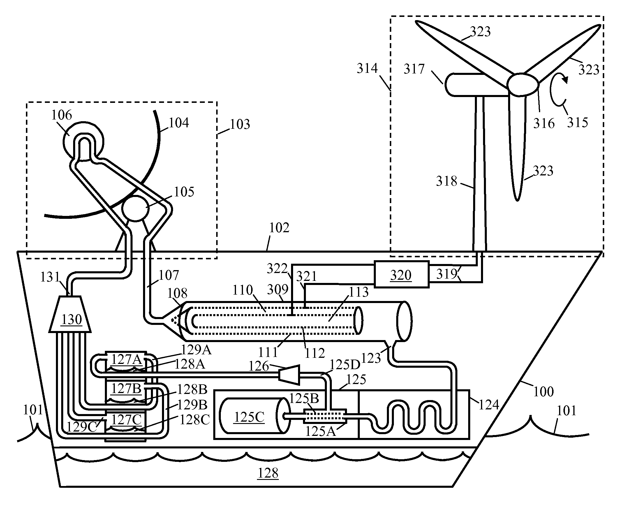
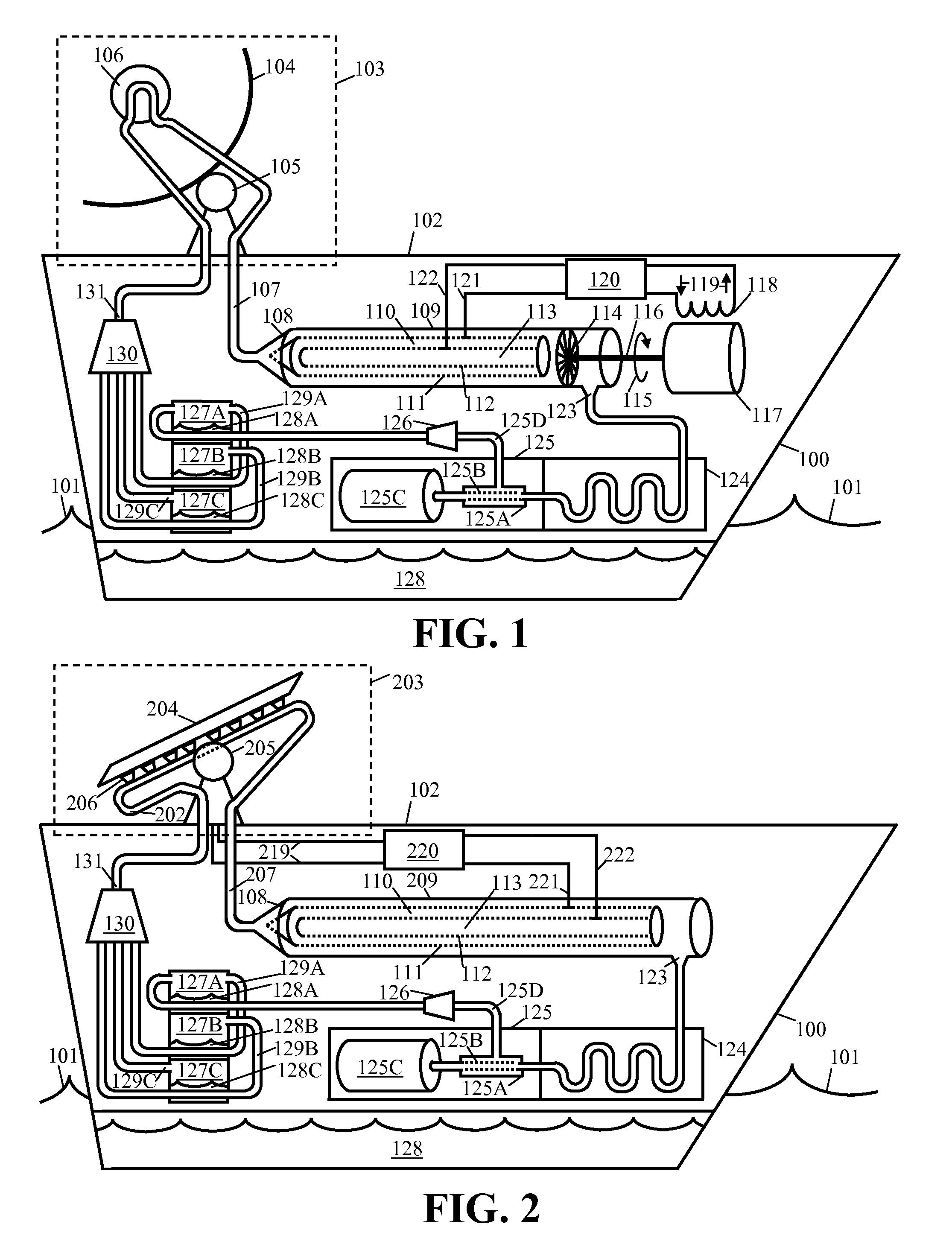
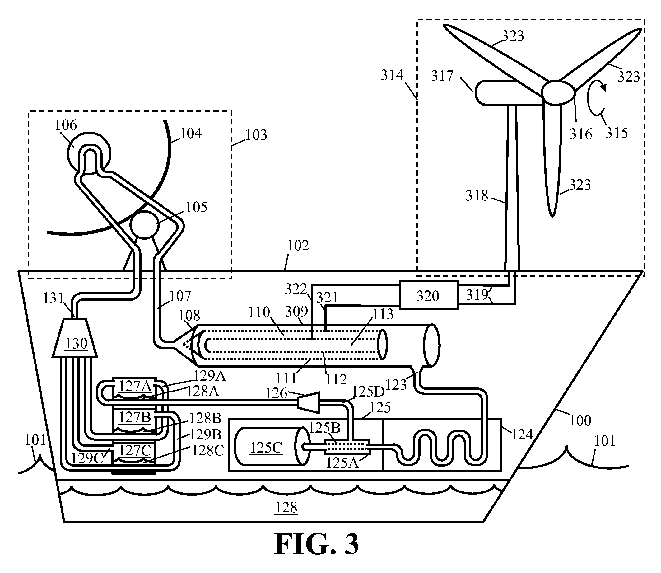
[0022]The present invention pertains to a mobile buoyant energy recovery system featuring novel solar heat management that ensures highly efficient energy storage and abundant feedstock in combination with a remote control system and algorithm for supervisory control and data acquisition enabling optimal configuration, navigation and autonomous operation of the system. The following description contains specific information pertaining to various embodiments and implementations of the invention. One skilled in the art will recognize that one may practice the present invention in a manner different from that specifically depicted in the present specification. Furthermore, the present specification need not represent some of the specific details of the present invention in order to not obscure the invention. A person of ordinary skill in the art would have knowledge of such specific details not described in the present specification. Others may omit or only partially implement some fea...


PUM


Abstract

An offshore vessel embodies a mobile buoyant energy recovery system enabled to extract energy from solar power. An exemplary energy recovery system comprises concentrating solar thermal power systems (CSP) or concentrating photovoltaic power (CPV) systems on the deck of the vessel. Within the vessel hull, ballast water serves multiple purposes. The ballast not only stabilizes the vessel, but also provides reactant for hydrogen electrolysis or ammonia synthesis, or steam for a turbine. For CPV systems the ballast conducts heat as a coolant improving the efficiency and durability of photovoltaic cells. For CSP systems the ballast water becomes superheated steam through a primary heat exchanger in the concentrator. In some embodiments, some steam from the CSP primary heat exchanger or from the CPV coolant system undergoes high-pressure electrolysis of enhanced efficiency due to its high temperature. In some embodiments, the remaining steam that did not undergo electrolysis drives a steam turbine providing electrical current for electrolysis. A secondary heat exchanger takes heat from the steam expelled from an energy storage process to efficiently distill ballast water at a lower temperature thus minimizing corrosion and build-up of scale. A remote control Supervisory Control and Data Acquisition System (SCADA) determines position, navigation, configuration, and operation of the preferably unmanned modular mobile buoyant energy recovery structure based on Geospatial Information Systems (GIS), Velocity Performance Prediction (VPP) models, Global Positioning Satellites (GPS) and various onboard sensors and controls.

Description

BACKGROUND OF THE INVENTION[0001]1. Field of the Invention[0002]The present invention is generally in the field of power cogeneration systems. More specifically, the present invention teaches a remote-controlled modular mobile buoyant solar cogeneration plant that optimally recovers and delivers energy from an offshore marine environment.[0003]2. Background Art[0004]Today while worldwide investment in solar power systems reaches ever-increasing proportions, technology has not addressed many physical and regulatory constraints that impede rapid deployment of utility-scale systems. The solar power system manufacturing industry now in its nascent stages risks overcapacity and subsequent consolidation despite energy demand actually increasing, unless technology soon enables rapid deployment.[0005]With the output of renewable energy systems primarily utilizing electrical current as the energy carrier, the existing electrical grid must accommodate an increase of capacity afforded by new d...

Claims


Application Information

Patent Timeline
IPC IPC(8): H01L31/058F24J2/38G06F17/00F24J2/04F24S50/20
CPCF03G6/00F24J2/5269Y02E10/46H02S40/44F24J2/40F24J2200/04Y02E10/47Y02E10/60F24S2201/00F24S20/70F24S50/00F24S30/422Y02E10/50
Inventor GIZARA, ANDREW ROMAN
Owner INTEGRATED POWER TECH CORP
Why Eureka
Try Eureka