

Radiative fibers
- Summary
- Abstract
- Description
- Claims
- Application Information
AI Technical Summary
Benefits of technology
Problems solved by technology
Method used
Image

Examples
working examples
Example 1
Materials
[0480]The following polymers are synthesized by employing the Suzuki coupling.
[0481]The reaction can be carried out according to synthetic methods well known to the person skilled in the art. The method is described, for example, in WO 2003 / 048225.
[0482]Polymer PB1, a blue emitting polymer, is a copolymer comprising the following monomers with mol % as indicated:
[0483]The molecular weight (MW) of the PBI is distributed between 200000 and 300000 g / mol.
[0484]Polymer PR1, a red emitting polymer, is a copolymer comprising the following monomers with mol % as indicated by the indices of the repeating units:
[0485]The molecular weight (MW) of the PR1 is distributed between 120000 and 720000 g / mol.
[0486]Polymer P3, used as interlayer, is a copolymer comprising the following repeating units:
[0487]The molecular weight (MW) of the resulting polymer P3 is distributed between 200000 to 300000 g / mol.
[0488]All polymers, PB1, PR1 and P3 are well soluble in toluene. Additionally, a...
example 2
Preparation of an OLEFC
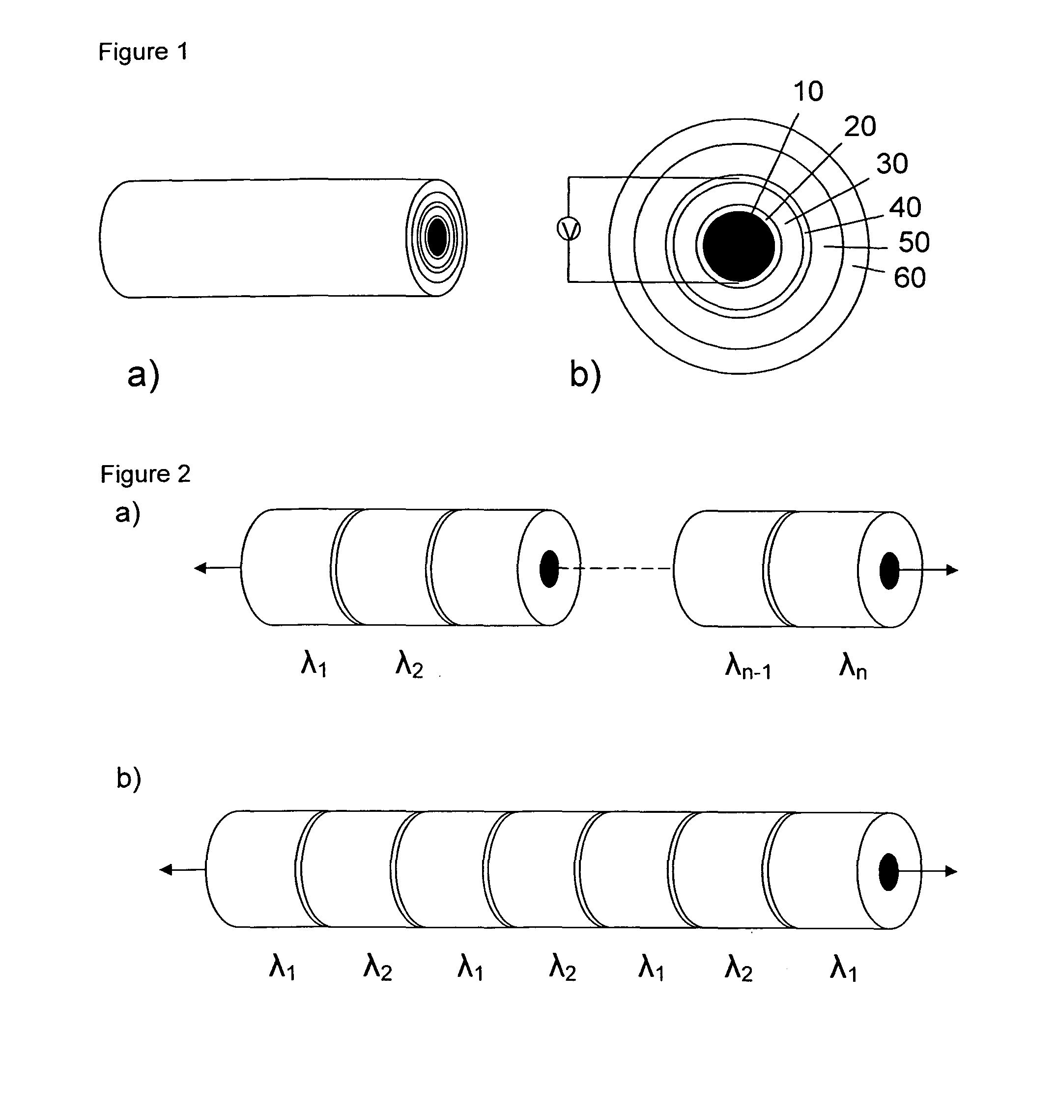
[0490]The fiber core 10 used in the present invention is a hard polymer-clad silica optical fiber (by CeramOptec Industries, Inc.), which has a silica core of 400 μm in diameter and 25 μm polyimide as jacket. Prior to the deposition of electrode, the fibers are cleaned successively by rubbing with a detergent, rinsing in deionized water, and cleaning by sonication in trichloroethylene, acetone and then isopropyl alcohol.
[0491]The fabrication steps I to VI are schematically depicted in FIG. 8.
Step I: Anode Deposition
[0492]The anode 20 is deposited conformally through a shadow mask using vacuum thermal evaporation at 107 Torr. The fibers are axially rotated at a speed of 60 rpm during the evaporation. Then, 150 nm A1 is evaporated on the cleaned fiber core 10 as first electrode (anode).
Step II: Buffer Layer 31 Deposition
[0493]PEDOT (Baytron P AI 4083) is deposited as buffer layer or hole injection layer (HIL) with a thickness of 80 nm onto the fiber by dip-coati...
example 3
Preparation of Plasters Comprising OLEFCs
[0505]The transparent flexible poly(ethylene naphthalate) (PEN) foil is used as substrate for the preparation of plasters.
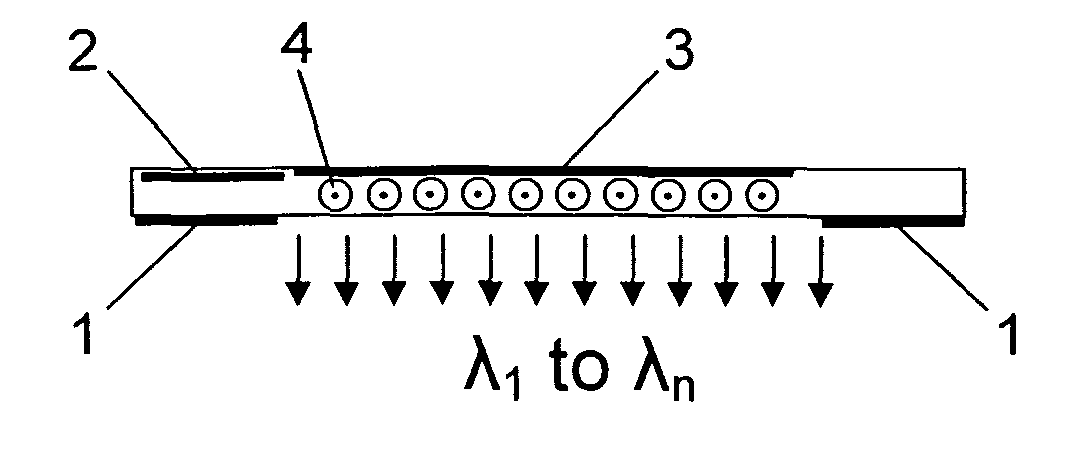
[0506]A plaster according to present invention is schematically shown in FIG. 12. The PEN substrate 300 has an area of ca. 5.5 cm×5.5 cm. The fiber OLECs 400 prepared in Example 2 are arranged in parallel in the middle of the substrate, with cathode 40 on one side and free anode 20 on the other side.
[0507]Then thin conducting wires 310 and 320 are connected to both the ends of the cathodes ends and the ends of the anodes of the OLEFCs with the help of silver conductive glue. The emissive area is defined in the middle area of the substrate, as marked by a dashed line in FIG. 12.
[0508]The device is then fixed and encapsulated by using UV-cured epoxy resin. UV Resin T-470C2, an advanced UV adhesives for OLED made by Nagase & Co., LTD, is applied to the area as marked as 330 in FIG. 12 being thick enough to cover all fibers on...
PUM
| Property | Measurement | Unit |
|---|---|---|
| Concentration | aaaaa | aaaaa |
| Concentration | aaaaa | aaaaa |
| Flexibility | aaaaa | aaaaa |
Abstract
Description
Claims
Application Information