

Carbon-coated lithium iron phosphate of olivine crystal structure and lithium secondary battery using the same
a lithium iron phosphate and olivine crystal technology, applied in the direction of cell components, final product manufacturing, sustainable manufacturing/processing, etc., can solve the problems of low stability and high cost, limitations of mass-use as a power source for electric automobiles, and linio/sub>2/sub>is unsuitable for practical application to mass-production at a reasonable cos
- Summary
- Abstract
- Description
- Claims
- Application Information
AI Technical Summary
Benefits of technology
Problems solved by technology
Method used
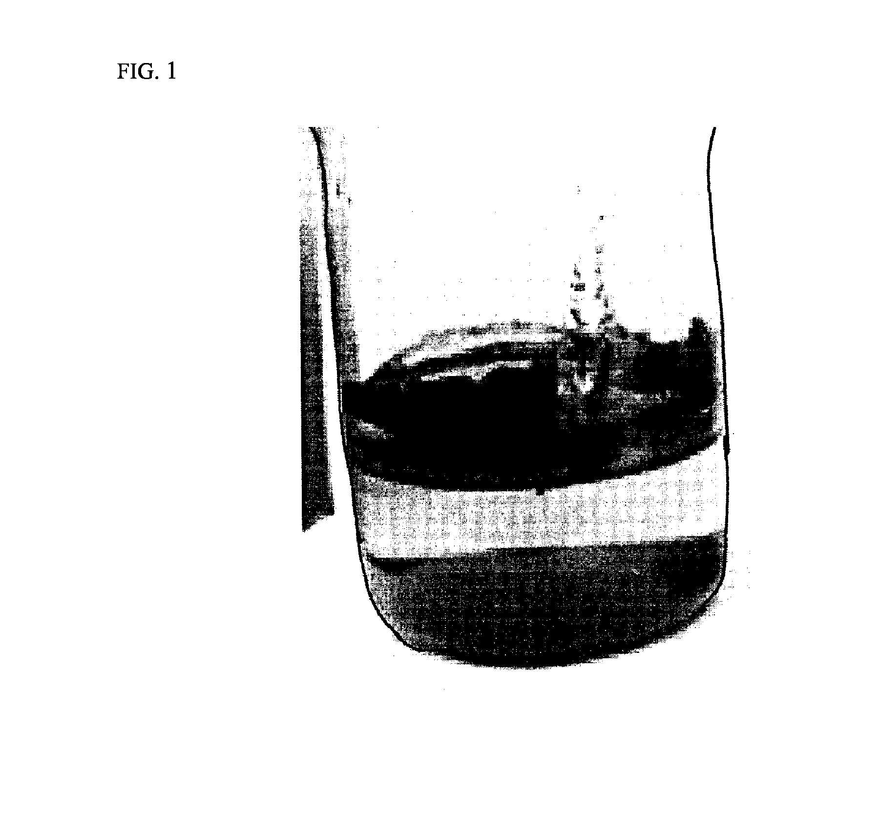
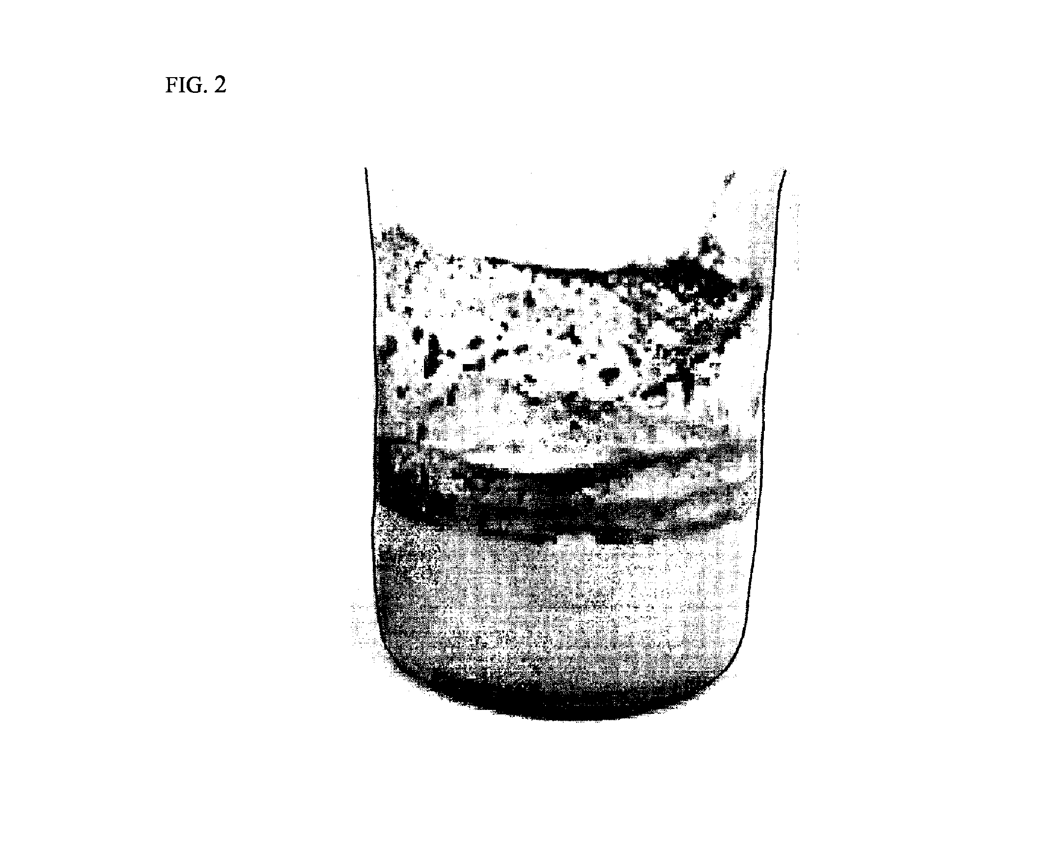
Image

Examples
example 2
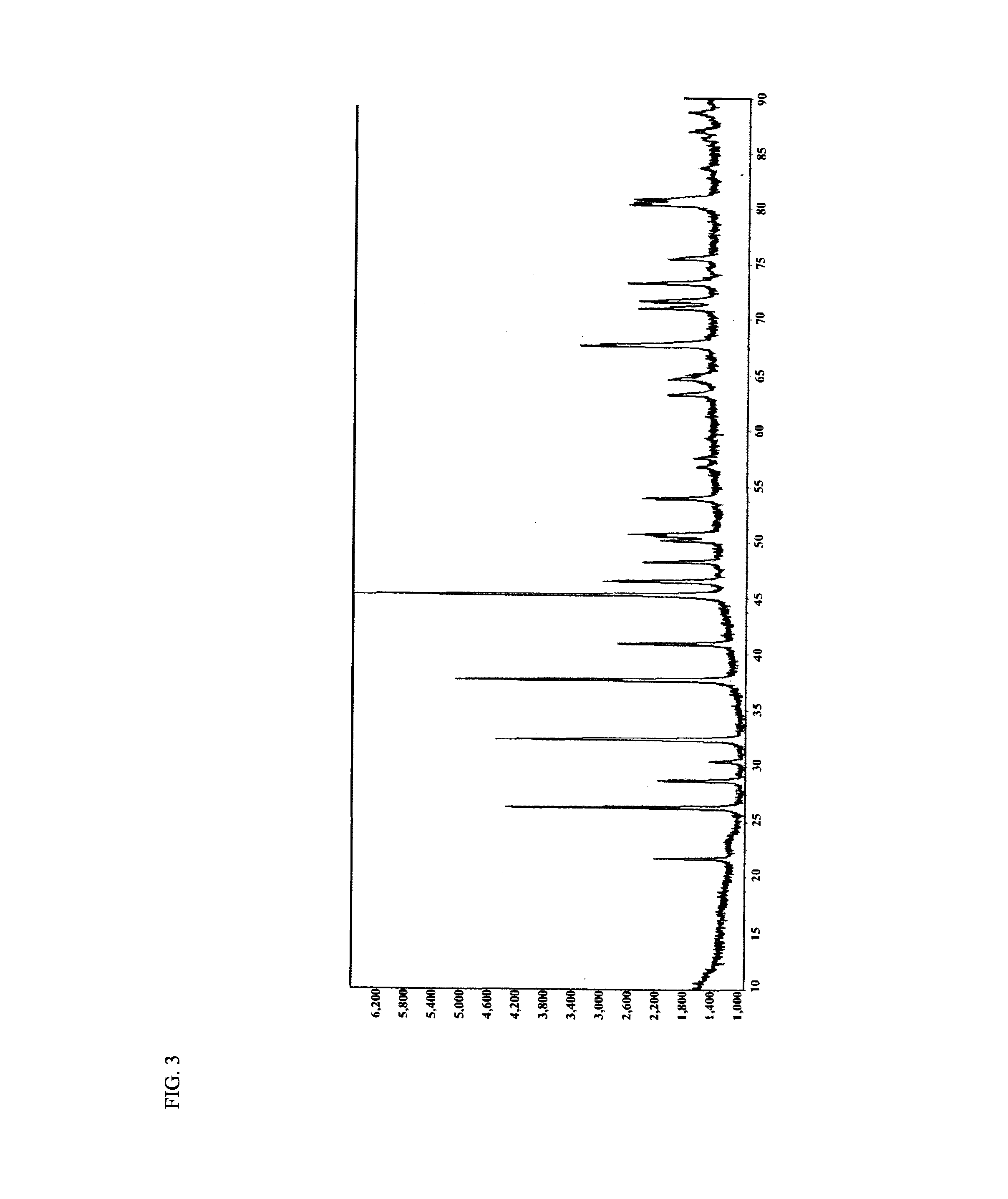
[0096]42.9 g of LiOH—H2O, 38.2 g of aqueous ammonia (˜29 wt %), and 918.9 g of distilled water were mixed with one another and dissolved to prepare an aqueous solution A. In the same manner as above, 141.3 g of FeSO4.7H2O, 14.13 g of sucrose, 57.7 g of phosphoric acid (85 wt %), and 793.94 g of distilled water were mixed with one another and dissolved to prepare an aqueous solution B. Supercritical water (450° C., 250 bar) was flowed at an elevated temperature and at an elevated pressure at 100 g / min into a continuous tubular reactor, and the aqueous solution A and the aqueous solution B were flowed at a flow rate of 15 g / min and brought in contact with the supercritical water for several seconds and mixed to induce reaction. At this time, the aqueous solution A first contacted the aqueous solution B to produce a slurry and was then reacted with the supercritical water. The aqueous solution A was reacted with supercritical water as soon as possible after production of slurry.
[0097]T...
example 3
[0100]42.9 g of LiOH—H2O, 44.1 g of aqueous ammonia (˜29 wt %), and 918.9 g of distilled water were mixed with one another and dissolved to prepare an aqueous solution A. In the same manner as above, 141.3 g of FeSO4.7H2O, 7.07 g of sucrose, 57.7 g of phosphoric acid (85 wt %), and 793.94 g of distilled water were mixed with one another and dissolved to prepare an aqueous solution B. Supercritical water (450° C., 250 bar) was flowed at an elevated temperature and at an elevated pressure at 100 g / min into a continuous tubular reactor, and the aqueous solution A and the aqueous solution B were flowed at a flow rate of 15 g / min and brought in contact with the supercritical water for several seconds and mixed to induce reaction. At this time, the aqueous solution A first contacted the aqueous solution B to produce a slurry and was then reacted with the supercritical water. The aqueous solution A was reacted with supercritical water as soon as possible after production of slurry.
[0101]Th...
example 4
[0104]42.9 g of LiOH—H2O, 44.1 g of aqueous ammonia (−29 wt %), and 918.9 g of distilled water were mixed with one another and dissolved to prepare an aqueous solution A. In the same manner as above, 141.3 g of FeSO4.7H2O, 7.07 g of sucrose, 57.7 g of phosphoric acid (85 wt %), and 801 g of distilled water were mixed with one another and dissolved to prepare an aqueous solution B. Supercritical water (450° C., 250 bar) was flowed at an elevated temperature and at an elevated pressure at 100 g / min into a continuous tubular reactor, and the aqueous solution A and the aqueous solution B were flowed at a flow rate of 15 g / min and brought in contact with the supercritical water for several seconds and mixed to induce reaction. At this time, the aqueous solution A first contacted the aqueous solution B to produce a slurry and was then reacted with the supercritical water. The aqueous solution A was reacted with supercritical water as soon as possible after production of slurry.
[0105]The L...
PUM
| Property | Measurement | Unit |
|---|---|---|
| thickness | aaaaa | aaaaa |
| volume density | aaaaa | aaaaa |
| thickness | aaaaa | aaaaa |
Abstract
Description
Claims
Application Information