

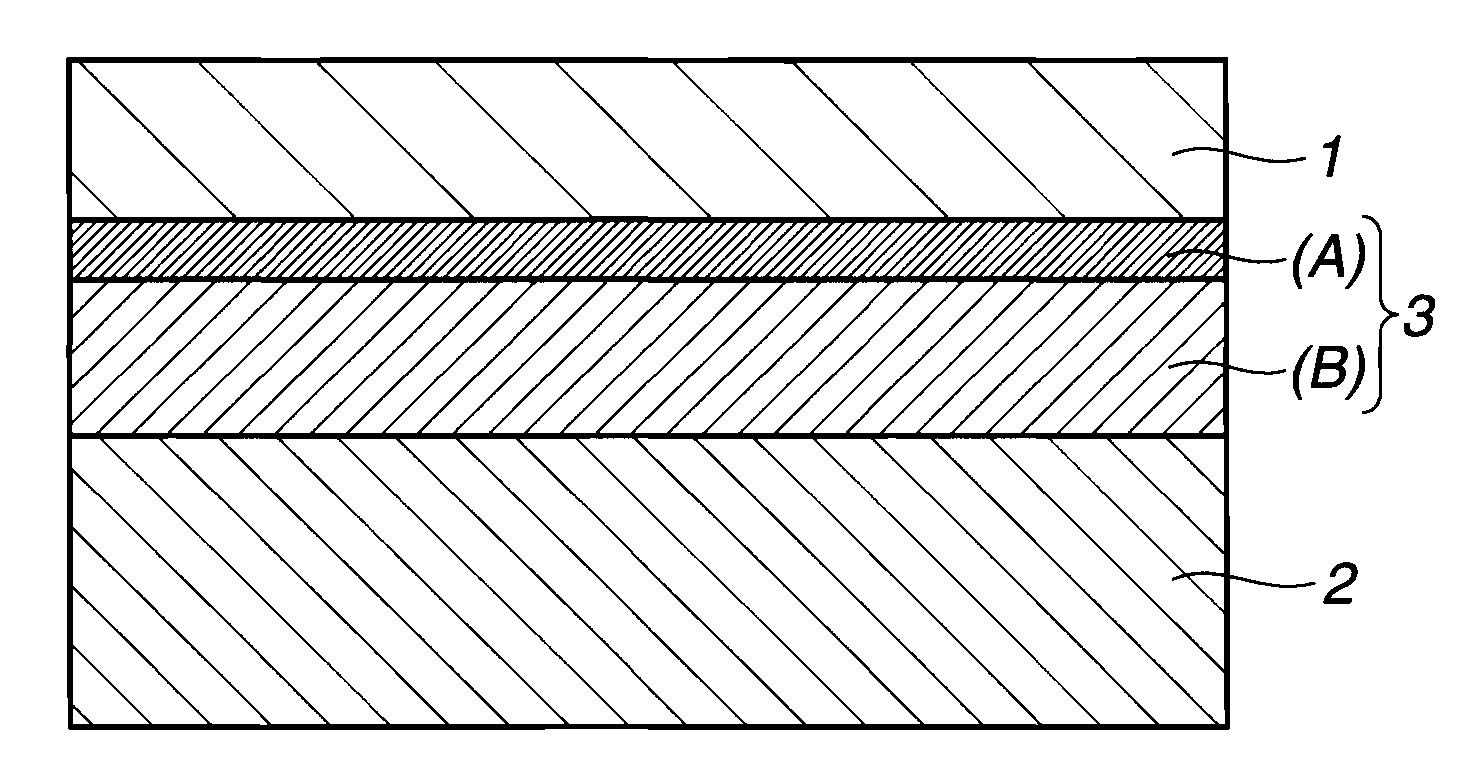
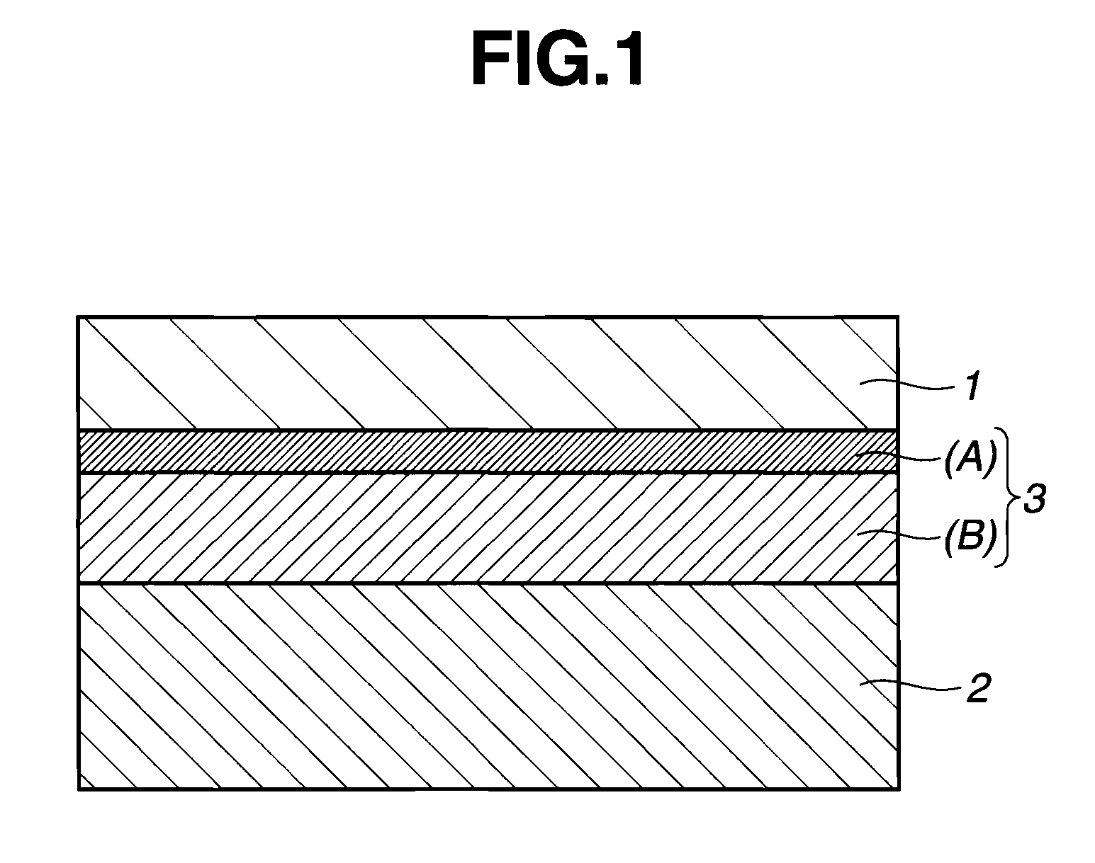
Wafer processing laminate, wafer processing member, temporary bonding arrangement, and thin wafer manufacturing method
- Summary
- Abstract
- Description
- Claims
- Application Information
AI Technical Summary
Benefits of technology
Problems solved by technology
Method used
Image

Examples
synthesis example 1
Resin Synthesis Example 1
[0059]A four-necked flask was charged with 1,000 g (3.38 mol) of octamethylcyclotetrasiloxane and 0.24 g (0.0015 mol) of hexamethyldisiloxane and heated at a temperature of 110° C. Then, 4 g of 10 wt % tetrabutylphosphonium hydroxide siliconate was added to the flask whereupon polymerization was performed over 4 hours. The product was post-treated at 160° C. for 2 hours, obtaining dimethylpolysiloxane.
[0060]The product was analyzed by 29Si-NMR spectroscopy to determine the contents of D and M units. It was identified to be a dimethylpolysiloxane of the following structure consisting of 99.978% of D units and 0.022% of M units and having a degree of polymerization of about 9,000.
[0061]This dimethylpolysiloxane, 500 g, was dissolved in 500 g of hexane. This was poured into 2 L of acetone whereupon a precipitated resin was recovered. On subsequent removal of hexane in vacuum, there was obtained a dimethylpolysiloxane polymer having a Mw of 700,000 and containin...
synthesis example 2
Resin Synthesis Example 2
[0062]A four-necked flask was charged with 1,000 g (3.38 mol) of octamethylcyclotetrasiloxane and 0.93 g (0.003 mol) of tris(trimethylsiloxy)methylsilane and heated at a temperature of 110° C. Then, 4 g of 10 wt % tetrabutylphosphonium hydroxide siliconate was added to the flask whereupon polymerization was performed over 4 hours. The product was post-treated at 160° C. for 2 hours, obtaining dimethylpolysiloxane.
[0063]The product was analyzed by 29Si-NMR spectroscopy to determine the contents of D, M and T units. It was identified to be a branched dimethylpolysiloxane of the following structure consisting of 99.911% of D units, 0.067% of M units, and 0.022% of T units.
[0064]This branched dimethylpolysiloxane, 500 g, was dissolved in 500 g of hexane. This was poured into 2 L of acetone whereupon a precipitated resin was recovered. On subsequent removal of hexane in vacuum, there was obtained a dimethylpolysiloxane polymer having a Mw of 400,000 and containin...
synthesis example 3
Resin Synthesis Example 3
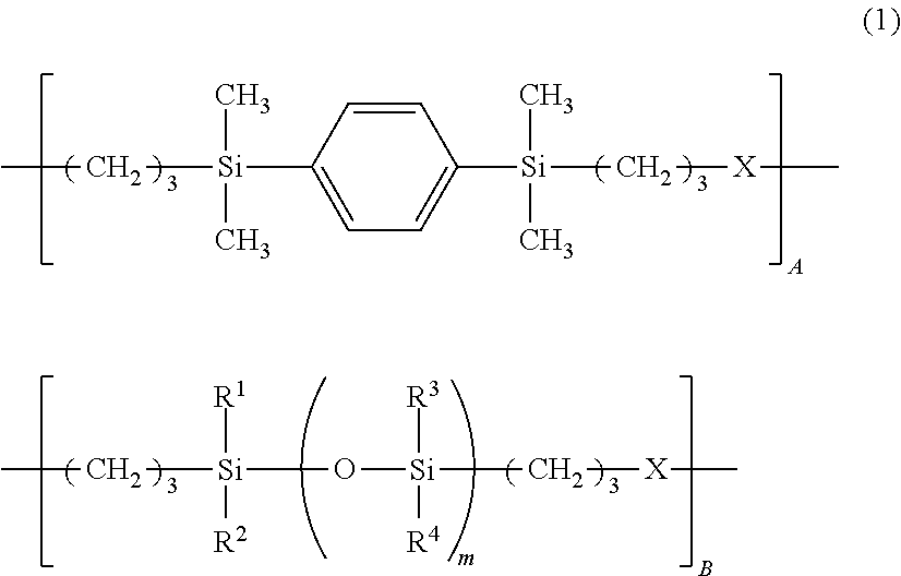
[0065]A flask equipped with a stirrer, thermometer, nitrogen purge line and reflux condenser was charged with 43.1 g of 9,9′-bis(3-allyl-4-hydroxyphenyl)fluorene (M-1), 29.5 g of organohydrogensiloxane having the average structural formula (M-3), 135 g of toluene, and 0.04 g of chloroplatinic acid and heated at 80° C. Then, 17.5 g of 1,4-bis(dimethylsilyl)benzene (M-5) was added dropwise to the flask over one hour while the flask internal temperature rose to 85° C. At the end of dropwise addition, the reaction solution was aged at 80° C. for 2 hours. Toluene was distilled off, and instead, 80 g of cyclohexanone was added, obtaining a resin solution in cyclohexanone having a resin solid concentration of 50 wt %. The molecular weight of the resin in the solution was determined by GPC versus polystyrene standards, finding a Mw of 45,000. To 50 g of the resin solution were added 5 g of hexamethoxymethylol melamine (Nikalac MW-390 by Sanwa Chemical Co., Ltd.) and...
PUM
| Property | Measurement | Unit |
|---|---|---|
| Percent by mass | aaaaa | aaaaa |
| Percent by mass | aaaaa | aaaaa |
| Percent by mass | aaaaa | aaaaa |
Abstract
Description
Claims
Application Information