Anode for secondary battery, anode current collector, production method thereof, and secondary battery

a technology of anode current collector and secondary battery, which is applied in the manufacture of electrodes, solid-state diffusion coatings, and final product manufacturing processes, etc., can solve the problems of inability to anticipate large improvement in voltage source capacity with the current combination of cathode and anode active materials, and inability to meet the required performance as a portable power source. , to achieve the effect of high capacity, high economics,

Active Publication Date: 2013-05-09
FURUKAWA ELECTRIC CO LTD
View PDF2 Cites 33 Cited by
  • Summary
  • Abstract
  • Description
  • Claims
  • Application Information

AI Technical Summary

Benefits of technology

[0012]The anode for secondary battery of the present invention specifies the thickness of the silicon-type active material film formed on the surface of a current collector substrate, for which copper foil is used. Since the parameter and range of the fine surface configuration are specified by the lightness Y value in a XYZ colorimetric system, which can be considered a parameter for the surface configuration and the size of the actual surface area, including the microscopic voids of the fine roughened surface configuration of the electrode on which the film is formed. Thus, the large actual capacity and the reaction site for Li ion and the active material during charge and discharge is secured and electrochemical alloying and de-alloying of Li ion can take place without hindrance due to volume expansion and contraction. As a result, there is an effect in that the ratio of decrease in charge and discharge capacity, even after long repeated cycles, is smaller compared to that conventionally possible. Since the active material film contains silicon, high capacity is obtained. Furthermore, since silicon films obtained by the CVD method and electron beam evaporation method, etc. are used, even though the surface is rough, a uniform homogeneous active material film can be formed, which is industrially economical. Further, since an active material layer that is obtained by applying and calcinating a slurry can also be used, it is highly economical. Also, by adding phosphorus and oxygen or hydrogen to the silicon-type active material, the conductivity and the current collectivity of the active material and the entire electrode improve. Further, since atoms with similar to larger atomic radii exist between the silicon atoms, the lattice and atomic interval expand. Thus, Li ion, which has a large atomic radius and large ionic radius, can easily be inserted for alloying or desorbed for de-alloying, and excellent charge and discharge cycle life, as well as excellent charge and discharge characteristics at high rate, are obtained. Furthermore, by forming a heat-resistant layer and an anti-corrosion layer, as well as a silane coupling treatment layer, on the copper foil constituting the current collector, the ability to prevent time degradation until the formation of active material, and heat resistance under high temperature environment during film formation, can be maintained. Also, the adhesion between the active material film formed and the current collector surface improves. Moreover, such layers suppress the copper component in the current collector from diffusing into the silicon-type active material film, the decrease in charge and discharge capacity due to diffusion alloying of the active material with copper can be prevented, thus allowing high specific capacity that is inherent to silicon to be obtained. The secondary battery that utilizes the above described anode can obtain high capacity and long service life. Further, by using an electrolyte comprising a non-aqueous solvent containing fluorine, a secondary battery, in which degradation of capacity at repeated charge and discharge is much lower, can be obtained.

Problems solved by technology

However, Li-ion secondary battery by the combination of lithium cobalt oxide (LiCoO2)-type cathode active material and carbon-type anode active material mainly composed of graphite, which is currently used as standard Li-ion battery, is incapable of sufficiently supplying the amount of electricity required for today's high-functionality high-intensity electronic parts at a length of time, and is not able to fulfill the required performance as a portable power source.
Further, the carbon-type anode, of which its performance has been rising little by little every year, is also approaching the theoretical specific capacity, and it is becoming impossible to anticipate large improvement in voltage source capacity with the current combination of cathode and anode active materials.
There appears to be a limitation in meeting requirements for high-functionality and long mobile running of electronic devices, for loading on to industrial applications such as electric power tools, uninterruptible power sources, and electric storage devices, for which adoption is spreading, or for electric-powered vehicles.
In particular, Si has a specific capacity that is comparable to that of metallic Li, which is said to be difficult to put to practical use, and is thus, being the center of study.
Even if its initial charge capacity is large, if the chargeable capacity or dischargeable capacity decreases immediately after repeated charge and discharge, its operation life is short, and its value as a secondary battery becomes low.
However, in Si and other metal-type anode active materials, there is a problem in that their charge-discharge life is short.
The cause of such problem lies in that the adherence between the current collector and the active material is small, and thus, as a means to solve this problem, specification of the surface configuration of the current collector, as well as compositions wherein the current collector component is diffused into or alloyed with the active material film, are being used (for example, see Patent Document 1 or 2).

Method used


Image

  • Anode for secondary battery, anode current collector, production method thereof, and secondary battery
  • Anode for secondary battery, anode current collector, production method thereof, and secondary battery
  • Anode for secondary battery, anode current collector, production method thereof, and secondary battery

Examples


example

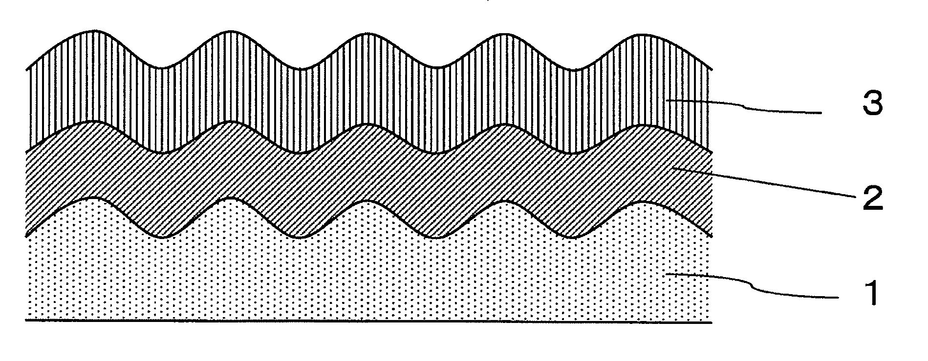
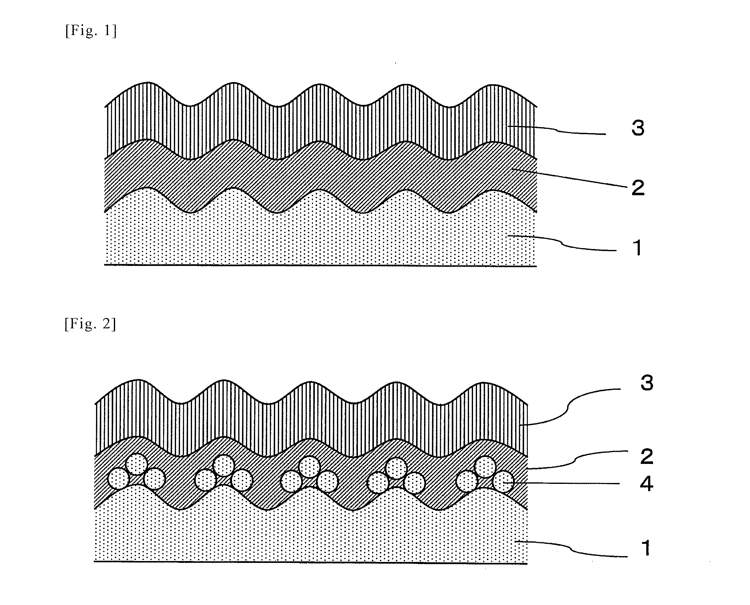
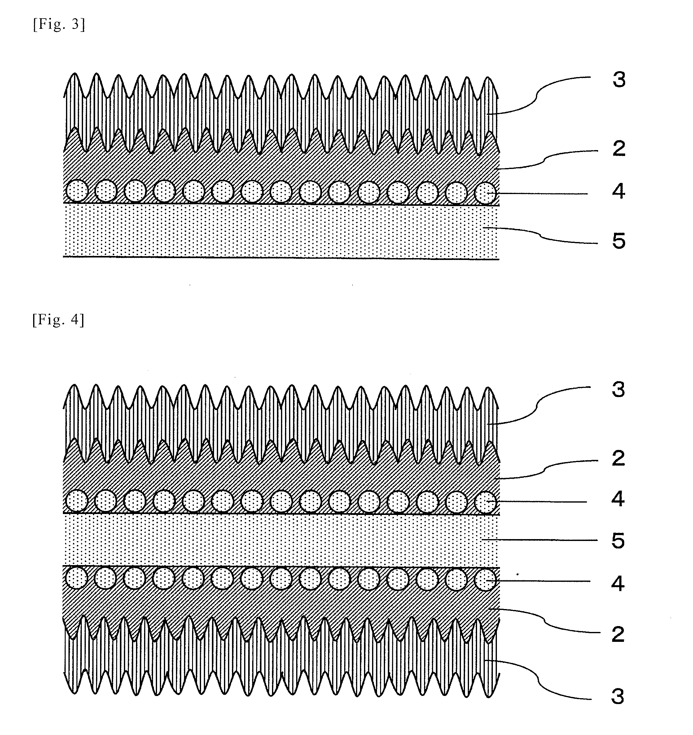
[0043]Hereinafter, the present invention will be described in detail with reference to the Examples. In this Example, the invention comprising a film on one side, as described in FIGS. 1 to 3, is shown. However, the present invention is not limited to such examples and the embodiment of FIG. 4, wherein the film formation treatment for one side is performed on both sides, may be similarly performed.

(1) Sample Preparation for the Examples and Comparative Examples

[0044]First, a test sample of the silicon-type anode of the present invention, and the anode current collector used for the same, as well as a silicon-type anode sample for comparison, were prepared as follows.

[0045]Rolled copper foil (Product of Nippon Foil Mfg. Ltd.) and electrolytic copper foil (product of Furukawa Electric Co. Ltd.) of various thicknesses were used as the original copper foil (copper foil substrate without surface treatment) for the current collector copper foil. For the rolled copper foil, a double-glossy...


PUM

PropertyMeasurementUnit
surface roughnessaaaaaaaaaa
tensile strengthaaaaaaaaaa

Abstract

A chargeable and dischargeable secondary battery for use in electronic devices, industrial machines, electric-powered vehicles, is provided, along with an anodic electrode and a copper foil for anode current collector. It is an anode for secondary battery that utilizes non-aqueous electrolyte, which comprises a silicon-type active material film formed on one side or both sides of a current collector made of copper foil or copper alloy foil, wherein 1 g / m2 to 14 g / m2 of silicon-type active material film is formed on said current collector, and the lightness Y value in a XYZ colorimetric system (CIE 1931 standard colorimetric system) for the surface of said anode, onto which said silicon-type active material film is formed, is 15 to 50, and the surface roughness (ten point average roughness) Rz specified by the Japanese Industrial Standards (JIS B0601-1994 ten point average roughness) is 1.0 μm or more and 4.5 μm or less.

Description

TECHNICAL FIELD[0001]The present invention relates to an anodic electrode and an anode current collector, which are used in chargeable and dischargeable secondary batteries, especially lithium ion secondary batteries that utilize non-aqueous electrolyte.BACKGROUND ART[0002]In recent years, with the mobilization and high functionality of electronic equipments, the secondary battery, which is a power source, has become one of the most important parts. In particular, lithium (Li) ion secondary battery has become the mainstream in place of conventional NiCd battery and Ni—H battery, due to its high energy density obtained from the high voltage of the cathode active material and anode active material. However, Li-ion secondary battery by the combination of lithium cobalt oxide (LiCoO2)-type cathode active material and carbon-type anode active material mainly composed of graphite, which is currently used as standard Li-ion battery, is incapable of sufficiently supplying the amount of elec...

Claims


Application Information

Patent Timeline
Patent Type & Authority Applications(United States)
IPC IPC(8): H01M4/66H01M4/04
CPCH01M4/0404H01M4/134H01M4/1395H01M4/364Y02T10/7011H01M4/70H01M10/052Y02E60/122H01M4/661Y02E60/10Y02T10/70Y02P70/50
Inventor TANI, TOSHIOYOSHINARI, KIYOSHISUZUKI, AKITOSHISHINOZAKI, KENSAKU
Owner FURUKAWA ELECTRIC CO LTD
Why Eureka
Try Eureka